 Image 1 |
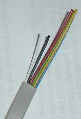 Image 2 |
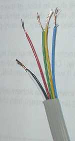 Image 3 |
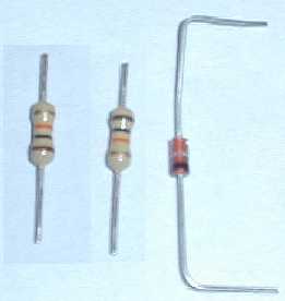 Image 4 |
Step 1
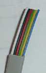
Trim away about 3/4 inch of the cable coating from one end (image 1) and
about 1.5 inch from the other end and cut short the black and white wires
(image 2). Using wire stippers, strip back about 1/4 inch of the coating
on each of the individual wires, then twist the black and white wires
together (image 3).
Image 1 |
Image 2 |
Image 3 |
Image 4 |
Step 2
Cut down the two resistors to size, and bend the diode into shape to fit
between pins 2 and 11 of the DB25 connector (image 4 - above). See the
connections diagram below (image 5) to see how these will all fit together.
 Image 5 |
Step 3
1. Solder the black and white wires together.
2. Put some melted solder into cups 2, 3, 4 and 11 of the DB25 connector.
3. Solder the two resistors into cups 3 and 4.
4. Solder the green wire into cup 11.
5. Solder the diode into cups 2 and 11. Note that the solid black bar on the
diode should be closest to cup 2. Also, shape the diode so that the part that
connects to cup 2 crosses the solid portion of the two resistors, so that no
electrical contact is made.
6. Put some melted solder onto the free ends of the two resistors, then solder
the yellow and blue wires to them. The blue wire connecting to the resistor in
cup 3 and the yellow wire connecting to the resistor in cup 4.
7. Turn the DB25 connector over and put some melted solder in cup 25, then solder
red wire red wire into this cup.
When this step is complete, your cable should look like this....
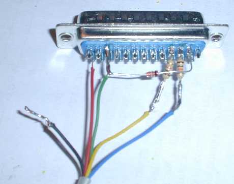 Image 6 |
Step 4
You should now use electrical tape to close off the black and white wires that
have been soldered together and to make sure that all the other parts cannot
touch each other. You should now take the two wire holders and clamp them onto
the cable, you should turn one of them the wrong way around so that they can
effectively clamp this cable, as it's much thinner than the cable they were intended
for. Then you can fit the DB25 connector into one half of the DB25
shell (as seen in image 7). Before you close up the DB25 shell, take the two screws
that have a ridge in the middle and insert them into the two square shaped washers,
then position these two screws into the holes on either side of the DB25 connector.
Now position the other half of the DB25 shell in place and use the remaining two
screws and nuts finish it.
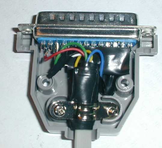 Image 7 |
Step 5
The final step is attaching the IDC connector. First, pop off the clamping bridge from
the IDC connector. Then position the wires onto the groves for each pin, be sure to have
the side of the IDC that has the groove cut away facing you, then you can see the triangle
arrow that indicates pin 1. Be sure to position the white wire on pin 1, and have the cut
end of the wires facing you at this point also. Then re-attaching the clamping bridge and
push it down until it clicks into place (making sure that you don't dislodge any of the wires
from their position while doing this).
Now, bend the wires back across the top of the clamping bridge and attach the strain relief over them, and push this down until it clicks into place. (images for this part coming soon). Congratulations, you have now built your interface cable, now it's time to test it!
If it doesn't work, refer to the troubleshooting guide in Tommy Tyler's "Simple Interface" instructions.
|
|