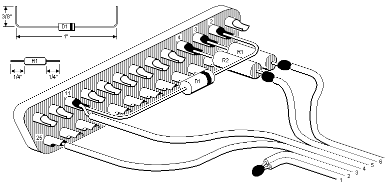
Figure 1. Assembly of Components and Connector
Simple Interface Rev 4.1
You can also download the current "Revision 5" version of this design in either MS Word or PDF formats.
1. REVISIONS. This version of the Simple interface is improved by using 1K resistors instead of 10K for R1 and R2 and by recommending a Schottky Diode 1N5818 instead of a signal diode 1N4148.
2. GENERAL DESCRIPTION. The Simple interface eliminates the buffer amplifiers of previous designs and instead connects signal lines to/from the PC's parallel port directly to the remote control. It is fully compatible with all existing software (IR.exe and RemoteIf.exe) and works with either 3-volt or 6-volt remotes. The interface will pass the "Check interface" test with or without batteries installed, but to upload or download memory requires batteries. Under certain circumstances you may not be able to operate the remote control while it is connected to the interface. This won't make any difference if all you want is the capability to upload or download, and don't mind unplugging JP1 to test your programming. Section 5 explains why this might occur and what you can do about it.
3. ASSEMBLY. The following parts are required:
| ITEM | QTY | DESCRIPTION |
|---|---|---|
| 1. | 1 | DB25 male connector with either solder pins or crimp connections |
| 2. | 1 | DB25 connector hood, any size or shape |
| 3. | 1 | Signal diode 1N4148 (Radio Shack 276-1122) or Schottky Diode 1N5818 (see note below) |
| 4. | 2 | Resistor, 1K 1/4W (Radio Shack 271-1321) |
| 4. | 2 | 6-hole IDC connector (Mouser 649-71602-306) |
NOTE: regarding the diode, using a signal diode should be sufficient for most desktop PCs but if you are using a laptop it is strongly recommended that you use a Schottky diode instead. The Schottky diode will work with both desktops and laptops, so obviously it's the better choice.
If you can't find the 6-hole IDC connector, one popular approach is to use a surplus ribbon cable assembly with IDC connectors, such as an IDE disk drive cable, saw off a 1/2-inch length of connector and leave contacts for just six wires in the center. Refer to the file entitled "6PinConnector.zip" in the Files/Interface Designs section at the JP1 site. The cable should be no longer than six feet.

Figure 1. Assembly of Components and Connector
Pre-cut and form component leads as shown in Figure 1. Solder the parts in whatever sequence you like. When placing the connector in the hood (see Figure 2.) make sure none of the component leads are touching unused connector pins or other leads. If you use a metal or metallized plastic hood be particularly careful that the solder joint of the wires from JP1-1 and 2 can't touch the hood.

Figure 2. Final Assembly of Interface
When using a ribbon cable the best way to provide strain relief is to use the cable clamp supplied with the hood, but reverse one of the clamps so the two nest with each other. Don't over-tighten the clamp or it may squeeze through the insulation over time and short out the wires. Better yet, add some insulation material between the clamp and ribbon cable, such as a few layers of electrical tape.
4. TESTING. A good visual inspection is all that's needed. Double check the pin numbers and the polarity of the diode. Leave the batteries out of the remote until you can pass the "Check interface" test, then install batteries and try a download. See Section 7 if you have problems.
5. SPECIAL INSTRUCTIONS REGARDING USE. It is recommended that you not leave a remote with batteries connected to an interface that is not plugged into a parallel port. Under those conditions the RESET line is not terminated, and noise can sometimes cause it to oscillate. This doesn't harm the remote, but can shorten battery life by continually blinking the red LED.
If your computer has parallel port output signals of only 3.5 volts or less, as some laptops do, and you are working with a 6-volt remote, the computer's output voltage is not high enough to release the reset signal on the remote's processor, so the processor remains reset as long as the remote is connected. This doesn't interfere with upload or download because the processor must be held reset during those operations anyway. But it means the JP1 connector must be unplugged before the remote can be operated. If you are one of the few users who absolutely must be able to operate the remote while it is still plugged into the interface the remedy is to reduce the operating voltage of the 6-volt remote to 4.5 volts by replacing one battery with a dead battery or a dummy. You can make a dummy by cutting a 1-3/4 inch length of 3/8 inch diameter wooden dowel rod and wrapping it with aluminum foil or aluminum tape.
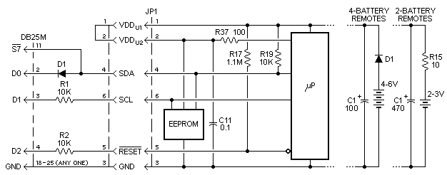
6. SCHEMATIC AND OPERATION. As shown in the schematic below, the RESET line is controlled directly by the D2 output of the parallel port. Resistor R2 limits current into the reset pin when the remote is operating at a

Figure 3. Schematic of Simple Interface Connected to Remote
lower voltage than the computer. The D1 output line is isolated from the SCL line by resistor R1 so that the processor can send clock signals to the EEPROM regardless of the status of D1, and D1 can send clock signals to the EEPROM when the processor output is in tri-state (reset). The DØ output line is connected to the SDA line through a diode. When DØ is high the diode is reverse biased. Under this condition the processor can send and receive data on the SDA line, or the EEPROM can send data to the PC on the S7 line. When the processor output is in tri-state a low on DØ will pull down on the SDA line and a high will let R19 pull up on it, which allows the PC to send data to the EEPROM.
7. TROUBLESHOOTING. If you're having trouble with your newly-built interface here are some troubleshooting tips that should help get you up and running. The two most common problems are:
(1) Failure to pass the "Check interface" test, resulting in error message "The remote interface check failed"
(2) Failure to download, resulting in error message "Header read failed, errno=1"
The "Check interface" test is a sort of crude communications test to verify that there is an interface out there at the specified parallel port address. It makes no difference whether a remote is connected. The test consists of toggling the DØ output up and down and making sure the S7 input follows it. Problem (1) means simply that the IR program is unable to communicate with the interface because S7 doesn't echo DØ. So you must solve this problem before you go on to see if you have problem (2).
The most likely cause of problem (1) is that you've plugged the interface into a parallel port whose address is something other than the default address of the IR program (378h). That's easily fixed by selecting the correct parallel port address in the Configuration pull down menu. And while you're at it, set the Transmission Delay to 800 to be sure we're not outrunning the interface. If you've done these things and the test still fails the problem must be "under the hood". Fortunately, the interface has so few parts that finding the cause of the problem is usually not very difficult. Remove the connector hood so you can see everything, and if you have an extender cable that will bring the interface out where you can get to it easily, all the better. Just be sure not to use a null modem cable as these have pins 2 and 3 swapped from one end to the other, and many don't even have connections to pins 11 and 25. If you use an extender cable make absolutely sure it has continuity between pins 2, 3, 4, 11, and 25 from one end to the other. None of the other pins matter.
You may be surprised to learn that the only component in the entire assembly required to pass the "Check interface" test is diode (D1), which must be installed the with its cathode (banded end) connected to pin 2 of the DB25 connector and the other end connected to pin 11. Also, the wire attached to the diode must not be making contact with anything other than pin 4 of JP1. To determine whether the diode is faulty or installed backwards try the Check test again while shorting out the diode with a piece of wire. If the test passes when the diode is shorted but fails when it is not, replace the diode. If the test fails even when the diode is shorted the only possibility is that what you think are pins 2 and 11 of the DB25 connector are not really pins 2 and 11, or they are not making contact with the PC connector. If you can't pass this test with pins 2 and 11 of your parallel port tied together there's a problem with your computer or the way your parallel port is setup.
Problem (2) means simply that the IR program is unable to communicate with the remote. Usually if you're having problem (1) but you ignore that and go ahead and try a download anyway, you'll get problem (2). Obviously, if IR can't talk to the interface it sure as heck can't talk to the remote. So we'll proceed under the assumption you're having problem (2) but not problem (1). The odds are 10-to-1 that the problem is with your cable and/or JP1 connector. So first make sure the connections from your ribbon cable (or whatever cable wires you are using) to the female pins in the JP1 connector are intact. You should check continuity between the end of each wire inside the interface hood and its corresponding contact inside the JP1 connector. Always use the lead wire of a 1/4-watt resistor as a probe for inserting into a JP1 contact. Never insert paper clips or other wires larger than 1/4-watt resistor leads because you may spread the tiny sockets so they make poor or intermittent contact with the pins in the remote.
If you have used ribbon cable and an IDC connector in your construction there are a few traps you may have fallen into. Since ribbon cable wires aren't color-coded it's easy to get them mixed up. And if the cable isn't positioned carefully before squeezing the cover down, some of the tiny contact barbs can miss the conductors or get bent over. If you made your IDC connector by sawing off a piece of a longer one you may have inadvertently cut it so that the left end starts with an even-numbered pin instead of an odd-numbered pin. In that case your upper and lower rows will be swapped. This mistake can't be fixed by bringing the cable out the other side. You must replace the connector. Study the JP1 connector diagram in Figure 2 and make sure you know where pin 1 should be.
If you're pretty sure the JP1 connector is OK and you've done the best visual inspection you can without having any luck, the following test may help narrow the problem down. You will need two JP1 contact probes made from 1/4-watt resistor lead wires. Insert one wire into pin 3 and the other into pin 4 of the JP1 connector (that's the middle two) and make sure they aren't touching each other. At this point the PC is connected to an interface whose JP1 cable isn't connected to anything but a couple of bare wires hanging in the breeze. When you initiate a download under these conditions you should get the bad header message.
Now hold the two wires together and try downloading again. If you receive a confirmation message that says "No definition file exists for this remote", that's good news. Click on YES to continue the download, and make sure you keep the two wires touching each other. In about two seconds the little red indicator at lower left of your screen should blink twice, signalling the completion of download, and the Raw Data page should be full of "ØØ"s.
Let's make the test a little more elaborate. Repeat the download, starting with the wires shorted together, but this time break contact between the wires about 1/4 to 1 second after you start the download. When the download completes, the first portion of Raw Data will be "ØØ"s and the last portion will be "FF"s. If you jiggle the wires after starting download so they make and break contact rapidly you'll get batches of "ØØ"s alternating with batches of "FF"s, with some intermediate bytes here and there. But if you jump the gun and break contact between the wires before download actually gets started you'll get the bad header message. What you are doing is fooling IR into thinking it's downloading a remote whose signature is "ØØ ØØ" (that's why the first few bytes must be with the wires shorted) and whose EEPROM data is mostly "FF"s (short removed). Passing this test doesn't ensure that your interface is 100% free of construction errors, but it sure gives you confidence that this thing is gonna work!.
In the above test, the only thing necessary to download a page full of "ØØ"s is to ground DB25-11, so if you don't get that result by shorting together the two probe wires in the above test the problem must be in either the wire from DB25-11 to pin JP1-4, or the wire from DB25-25 to JP1-3.
If you can download "ØØ"s and "FF"s in the above test but still get a bad header message when trying to download a remote with batteries, the problem might be either the resistor (R1) from DB25-3 and wire to JP1-6, or the resistor (R2) from DB25-4 and wire to JP1-5.
It's also very easy to mis-mate the JP1 connector when plugging it into the remote, and this is always the first thing you should check when there's trouble. For example, plugging the connector in so that it is shifted to the left one column of pins will result in a download of all "ØØ"s. Plugging it in shifted to the right one column or shifted up or down one row of pins causes a "Header read failure". Plugging it in upside down will result in a download of all "ØØ"s, etc. That's why so many members have devised means for ensuring the connector is inserted properly into the T-shaped opening in the remote. Some of these ideas are posted on the JP1 web site.
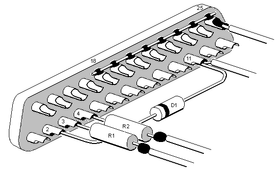
8. COMPUTERS HAVING NON-STANDARD GROUNDING OF PARALLEL PORT CONNECTOR. The standard specification for a parallel port connector calls for pins 18 through 25 to be tied to ground inside the computer. The interface requires pin 3 of the JP1 connector to be connected to at least one of these grounded pins, and the assembly instructions show the connection being made to pin 25 of the DB25 connector, which was selected arbitrarily. Several members have reported that while troubleshooting their recently-built interfaces they found pin 25 of their computer was NOT grounded. If you continue to have problems with your interface after exhausting all other troubleshooting ideas you might want to check this possibility. If you can determine which of pins 18 through 25 is/are grounded connect the wire from JP1-3 there. If you don't have the skills or equipment to measure this and want to eliminate the possibility that this may be causing your problem, lay a piece of wire across those pins and solder them all together, as shown below.

Figure 4. Tying Pins 18 Through 25 Together
|
|