A decade ago I bought an serial interface from DIYGADGET. I don't know if it was the JP1.1/2 or JP1.1/3 serial interface. I'm thinking it was the first one, although it works just great with JP1.3. I used the cable with a Dynex Serial/Usb Adapter. When the ribbon started to separate I bought a series of TommyTyler JP1.2/3 interfaces, but each worked for about 100 maybe 200 downloads (about 3 months) and then they quit. In the meantime that clunky diygadget with usb to serial adapter has been cranking along for thousands of uploads/downloads.
It just died. I don't know if it is the gadget or the adapter, but I'm now desperate. I've been half following where you guys have been doing something else for your cables, buying something from ebay. Is that something that's going to involve assembly? Do they last?
If I get the serial interface, with adapter, is there something to look (chipset) needed to make it work with the JP1 tools? When I plug the old one in, it says Prolific Usb to serial com port.
My interface died!!!!
Moderator: Moderators
-
vickyg2003
- Site Admin
- Posts: 7109
- Joined: Sat Mar 20, 2004 12:19 pm
- Location: Florida
- Contact:
My interface died!!!!
Remember to provide feedback to let us know how the problem was solved and share your upgrades.
Tip: When creating an upgrade, always include ALL functions from the oem remote, even if you never plan on assigning them to a button. Complete function lists makes an upgrade more helpful to others.
Tip: When creating an upgrade, always include ALL functions from the oem remote, even if you never plan on assigning them to a button. Complete function lists makes an upgrade more helpful to others.
-
The Robman
- Site Owner
- Posts: 21982
- Joined: Fri Aug 01, 2003 9:37 am
- Location: Chicago, IL
- Contact:
The following thread has all the info on the cable that we've all been using:
https://www.hifi-remote.com/forums/viewtopic.php?t=16360
This cable costs less than $10 shipped from China and usually gets here in about 2 weeks. As you can see from the image below, rather than having a conventional 6-hole connector, it has 6 individual 1-hole connectors. You can either replace these with a regular connector, or you can glue them together to form a single connector. But the cables do work and they are reliable.
Rob
www.hifi-remote.com
Please don't PM me with remote questions, post them in the forums so all the experts can help!
www.hifi-remote.com
Please don't PM me with remote questions, post them in the forums so all the experts can help!
-
vickyg2003
- Site Admin
- Posts: 7109
- Joined: Sat Mar 20, 2004 12:19 pm
- Location: Florida
- Contact:
So I can canibalize my parallel JP1 cable that and use that 6 pin connector.
NO Soldering, just crimping? Kind of like punching down all that ethernet, only I can do it in full sunlight so I might actually be able to see what I'm doing.
NO Soldering, just crimping? Kind of like punching down all that ethernet, only I can do it in full sunlight so I might actually be able to see what I'm doing.
Remember to provide feedback to let us know how the problem was solved and share your upgrades.
Tip: When creating an upgrade, always include ALL functions from the oem remote, even if you never plan on assigning them to a button. Complete function lists makes an upgrade more helpful to others.
Tip: When creating an upgrade, always include ALL functions from the oem remote, even if you never plan on assigning them to a button. Complete function lists makes an upgrade more helpful to others.
-
The Robman
- Site Owner
- Posts: 21982
- Joined: Fri Aug 01, 2003 9:37 am
- Location: Chicago, IL
- Contact:
Yup, no soldering, just crimping.
Rob
www.hifi-remote.com
Please don't PM me with remote questions, post them in the forums so all the experts can help!
www.hifi-remote.com
Please don't PM me with remote questions, post them in the forums so all the experts can help!
-
The Robman
- Site Owner
- Posts: 21982
- Joined: Fri Aug 01, 2003 9:37 am
- Location: Chicago, IL
- Contact:
True, if she has a more modern type of interface with the slimmer connectors, but if it's an older one with one of the older IDC connectors, then it's crimping.mdavej wrote:Technically not even crimping. Just press down the clips to pull out the old pins and snap in the new ones.
Rob
www.hifi-remote.com
Please don't PM me with remote questions, post them in the forums so all the experts can help!
www.hifi-remote.com
Please don't PM me with remote questions, post them in the forums so all the experts can help!
-
vickyg2003
- Site Admin
- Posts: 7109
- Joined: Sat Mar 20, 2004 12:19 pm
- Location: Florida
- Contact:
This has given me a total PANIC ATTACK! So I ordered one of those chippartner cables and one of DIY Gadgets JP1.2/1.3 serial cable. If the DIY gadget works, then my serial adapter went bad, and I'll buy a new adapter too. I have worked really hard to become JP1-self-sufficient. But when it comes to hardware, if my cable dies, I'm totally out of luck. So I back up my hardware. I have two widgets, 2 USB eeprom cables, but only 1 flash cable, because 3 $30 attempts to get one that works with the newer skinny openings all ended up failing with the kind of heavy duty required for extender and protocol development.
I have this connector on my old parallel cable and a similar connector on my serial cable that just died. I had to mark pin one on each because this one was assembled upside down by the supplier.
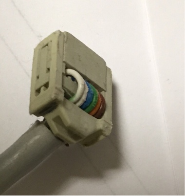
I also have this connector on an non-working flash cable. Is this possibly reusable. Until I read this post, I had forgotten that many of the remotes I support have that itsy-bitsy opening.
mdavej wrote:Technically not even crimping. Just press down the clips to pull out the old pins and snap in the new ones.
Rob wrote:True, if she has a more modern type of interface with the slimmer connectors, but if it's an older one with one of the older IDC connectors, then it's crimping.
I have this connector on my old parallel cable and a similar connector on my serial cable that just died. I had to mark pin one on each because this one was assembled upside down by the supplier.
I also have this connector on an non-working flash cable. Is this possibly reusable. Until I read this post, I had forgotten that many of the remotes I support have that itsy-bitsy opening.
Remember to provide feedback to let us know how the problem was solved and share your upgrades.
Tip: When creating an upgrade, always include ALL functions from the oem remote, even if you never plan on assigning them to a button. Complete function lists makes an upgrade more helpful to others.
Tip: When creating an upgrade, always include ALL functions from the oem remote, even if you never plan on assigning them to a button. Complete function lists makes an upgrade more helpful to others.
-
The Robman
- Site Owner
- Posts: 21982
- Joined: Fri Aug 01, 2003 9:37 am
- Location: Chicago, IL
- Contact:
I put one of those old crimp style connectors on the first chip_partner cable that I bought, so yes you can do that, but that connector is too big for many of the newer remotes.
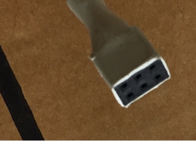
The second connector, wrapped in white, is the one that Dave was talking about. If you were to rip that white heat-shrink off it would look like the connector below. You can slide out the metal connectors, then slide out the metal connectors on the new cable and slide them into the plastic housing. You could also make it pretty by sliding a piece of heat shrink tubing over it, if you like.

The second connector, wrapped in white, is the one that Dave was talking about. If you were to rip that white heat-shrink off it would look like the connector below. You can slide out the metal connectors, then slide out the metal connectors on the new cable and slide them into the plastic housing. You could also make it pretty by sliding a piece of heat shrink tubing over it, if you like.
Rob
www.hifi-remote.com
Please don't PM me with remote questions, post them in the forums so all the experts can help!
www.hifi-remote.com
Please don't PM me with remote questions, post them in the forums so all the experts can help!
-
vickyg2003
- Site Admin
- Posts: 7109
- Joined: Sat Mar 20, 2004 12:19 pm
- Location: Florida
- Contact:
With two cables on order, I do feel a lot better.
I hope I can assemble that cable, but it doesn't sound like much fun. I see that DIYGadgets has an FTDI Flash cable with the small end already on it for 14.99. Is that what I'm going to be assembling? I'd easily spend $5, to avoid the assembly task.
Funny how hard I balked at buying my first interface back in the Yahoo days, and how now I have major panic when I don't have one.
Remember to provide feedback to let us know how the problem was solved and share your upgrades.
Tip: When creating an upgrade, always include ALL functions from the oem remote, even if you never plan on assigning them to a button. Complete function lists makes an upgrade more helpful to others.
Tip: When creating an upgrade, always include ALL functions from the oem remote, even if you never plan on assigning them to a button. Complete function lists makes an upgrade more helpful to others.
-
The Robman
- Site Owner
- Posts: 21982
- Joined: Fri Aug 01, 2003 9:37 am
- Location: Chicago, IL
- Contact:
I think the chip_partner cables are a lot more reliable than the DIY cables.
I think I have a 2nd chip_partner cable that I never modified, so maybe I will make a video showing just how easy it is to swap the connectors over to a 2*3 housing.
I think I have a 2nd chip_partner cable that I never modified, so maybe I will make a video showing just how easy it is to swap the connectors over to a 2*3 housing.
Rob
www.hifi-remote.com
Please don't PM me with remote questions, post them in the forums so all the experts can help!
www.hifi-remote.com
Please don't PM me with remote questions, post them in the forums so all the experts can help!
-
vickyg2003
- Site Admin
- Posts: 7109
- Joined: Sat Mar 20, 2004 12:19 pm
- Location: Florida
- Contact:
A video would be really nice.The Robman wrote: I think I have a 2nd chip_partner cable that I never modified, so maybe I will make a video showing just how easy it is to swap the connectors over to a 2*3 housing.
In the meantime I have a question about shrink wrapping the end on one of these things.
What size shrink wrap do I need if I want to give this a little more protection where those itsy bitsy wires stick out?
Remember to provide feedback to let us know how the problem was solved and share your upgrades.
Tip: When creating an upgrade, always include ALL functions from the oem remote, even if you never plan on assigning them to a button. Complete function lists makes an upgrade more helpful to others.
Tip: When creating an upgrade, always include ALL functions from the oem remote, even if you never plan on assigning them to a button. Complete function lists makes an upgrade more helpful to others.
Step 1 is to put all the connectors on and be SURE that they are positioned correctly. After that, I put them on an empty 6 pin header just to keep them oriented correctly. The correct size of heat shrink is one that fits loosely over the connectors. Next, I put some of this Shoe Goo where the wires enter the connectors. Then I put the heat shrink over the connectors and goo. Then I heat shrink starting at the header. As the tubing shrinks, a bit of the goo may come out at the wire end. When the goo hardens, it will keep the wires very solid near the connector. You can also find the same thing with the name "Goop" - should be available at any hardware store.
-
vickyg2003
- Site Admin
- Posts: 7109
- Joined: Sat Mar 20, 2004 12:19 pm
- Location: Florida
- Contact:
Thanks for all the information. I found the problem with my old serial interface was the adapter. Easy to determine when I had the new DIYGadget serial cable. So I got a new USB serial adapter, and then had two working interfaces, so this got pushed to the back burner.
I came in from the garden because it was too hot and decided to get my act toghether and assemble my cable.
Here are my results.
https://youtu.be/cLYzsh-usTo
I came in from the garden because it was too hot and decided to get my act toghether and assemble my cable.
Here are my results.
https://youtu.be/cLYzsh-usTo
Remember to provide feedback to let us know how the problem was solved and share your upgrades.
Tip: When creating an upgrade, always include ALL functions from the oem remote, even if you never plan on assigning them to a button. Complete function lists makes an upgrade more helpful to others.
Tip: When creating an upgrade, always include ALL functions from the oem remote, even if you never plan on assigning them to a button. Complete function lists makes an upgrade more helpful to others.