Protocol Builder
Protocol Builder (aka "PB") is a spreadsheet based program that is used to create new executors for JP1 remotes. An 'executor' is a piece of code used by a JP1 remote to replicate an infared protocol. The documents below describe how you can capture a new signal using your JP1 learning remote and build a new upgrade.
Before you start, you should download this zip file which contains some sample files referred to in the following docs.
Signal Specifics
First, look at the signals in the "Learned Signals" tab of IR.exe, then cut & paste the timing data over to a text editor (such as Notepad, etc). It would be helpful if the text editor allows you to perform global edits. The version of Notepad that ships with Windows 2000 does allow global edits, but earlier versions do not, in which case it might be a better idea to use Wordpad. Copy the data in the order that the buttons appear in the Learned Signals tab so you don't lose track of which button each set of data belongs to.
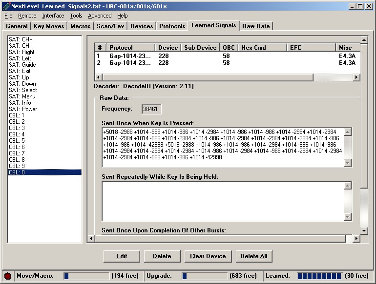
Image 1 – the “Learned Signals” tab in IR
When you have completed copying the data, you should have a file somewhat like the codes1.txt file included in this zip file. The next step is to try and clean up the signal times. IR tends to report the signal times very exactly, but in reality most devices have quite a large level of tolerance for signals not being exactly what they should be. So, what we need to do now is try and round all the numbers up or down so all similar numbers are actually the same. For example, if you see times like +988, +995, +1015, etc, they are all really the same time and can be rounded to +1000.
When you have finished rounding the numbers, you should end up with a file somewhat like codes2.txt in the zip file. The data in this file should be viewed as pairs, where a pair is a grouping of a ON time and an OFF time. The ON times are represented by positive numbers and the OFF times are represented by negative numbers. The next step is to attempt to identify the following pairs:
- Lead-in pair
- Logical "zero" pair
- Logical "one" pair
- Lead-out pair
Looking at the data in codes2.txt, you will notice that the first pair is "+5000 -3000" and then there is a mixture of the following two pairs "+1000 -1000" and "+1000 -3000", then eventually you will find a pair with a much bigger OFF time, and then the whole signal repeats. In all of these examples, the signal is repeated 2 times, and each repetition includes the lead-in and lead-out pairs.
Therefore, here's the data for the afore mentioned pairs:
- Lead-in pair = "+5000 -3000"
- Logical "zero" pair = "+1000 -1000"
- Logical "one" pair = "+1000 -3000"
- Lead-out pair = (to be determined)
Actually, there is no exact science to deciding which of the two variable pairs is the logical "one" and "zero" pairs. Generally speaking, the "zero" pair will have smaller times than the "one" pair, but even that's just a guess. Bottom line, it doesn't really matter. In fact, UEI gets it wrong more often than they get it right in their protocols.
So, now that we've guessed the "one" and "zero" pairs, let's edit the file so we can see the binary. My preferred way to do this is to edit the strings like this:
"+1000 -1000" --> 0^ "+1000 -3000" --> 1^
I put the ^ character after the number so that if I later decide I want to reverse the pairs and make the first pair the logical "one" I can edit all the 0^ and 1^ strings and reverse them. When you're done editing the "one" and "zero" pairs, you should end up with a file somewhat like codes3.txt You'll notice that I've inserted a space in the middle of the binary string, breaking it into two groups of 8. In the binary world, 8 is considered a round number, so you'll often find that the total length of the binary signal is a multiple of 8. In this case you should notice that the second string is constant for all the signals, so we can consider this to be our "device code". The first string is different for all the signals, so we can consider this to be our "command code".
While units of 8 are the most common, there are always exceptions to every rule. Your immediate goal is to determine which bits are constant for every signal and which bits vary. The more learned signals you have, the greater the chance that you will get this right.
At this point you should examine the data and see if you can spot any "compliments". A compliment code is where the data is the same as the previous data, only inverted. (Inverted, or complimented, means that if the original bit was 0, the new bit should be 1, and vice versa).
Normally, you would probably find that the lead-out pair is constant for all signals, but in this case it varies, which leads me to suspect that it's calculated as a result of the total signal length. Every "zero" pair lasts 2000 uSecs and every "one" pair lasts 4000 uSecs, so given that there are 16 bits in each of these signals, the data portion of the signal will last a minimum of 32000 uSecs (which would mean that the binary was all zeroes). Each "one" in the signal would add an additional 2000 uSecs to the total. If you calculate the total duration of the data portion of the signal and add in the lead-out times, you'll find that each signal lasts for a total of 98000 uSecs.
Entering Signal Specifics Into PB
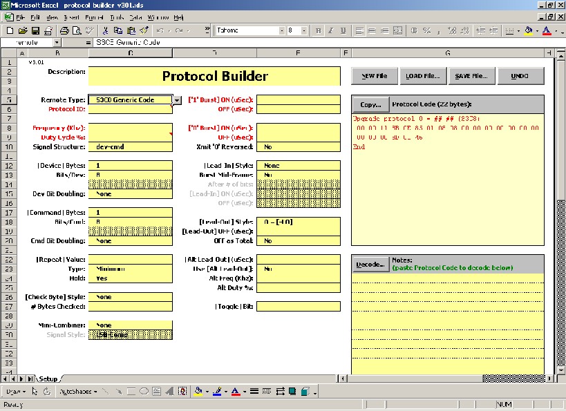
Now, let's move on to the PB spreadsheet itself, when you first open it, it looks like this:
And you thought KM was scary! Don't worry, just like KM this spreadsheet is actually easier to use than it looks. Now we have to start entering the data that we have just worked on.
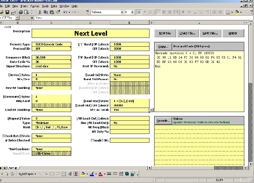
- Description: Very short description of the signal, our signals were for a "Next Level" cable box, so let's enter "Next Level".
- Remote Type: Generally speaking, you should leave this as "S3C8 Generic Code" as this covers most of the remote in use in the JP1 world. If you believe that you need one of the other options, but are not sure which one to use, you should post a question about it in the forums.
- Protocol Id: Basically, this can be whatever you want, but it's generally a good idea to use an id that is not already established as an official protocol id. You enter the code in hex format where 0 is the smallest value allowed and 1FF is the largest. So, I would advise that you use 1FF for this new protocol.
- Frequency: Enter the value displayed in IR's "Learned Signals" tab.
- Duty Cycle: There's no easy way to determine this, so use 30% unless you have reason to do otherwise.
- Signal Structure: This is determined by how the binary data is laid out. In our example, the command code came before the device code and there weren't any compliments involved, so we should select "cmd-dev".
- [Device] Bytes: this is the number of bytes of fixed data. In our example we found one fixed byte, so we will enter 1.
- Bits/Dev: this is how many bits are in each fixed byte. The max value is 8, which is also the most common answer. In our example, there are 8 fixed bits.
- [Command] Bytes: this is the number of bytes of variable data. In our example we found one variable byte, so we will enter 1.
- Bits/Cmd: this is how many bits are in each variable byte. The max value is 8, which is also the most common answer. In our example, there are 8 fixed bits.
- [Repeat] Value: this is the minimum number of times the signal should repeat. It appears from the data in our examples, that the signal should repeat at least 2 times.
- Type: when set to 'Minimum', item 10 above controls the minimum number of repeats, supposedly 'Forced' makes the signal repeat that many times only, but I understand this this setting is not reliable.
- Hold: this determines if the signal repeats, and if so, under what circumstances. "Yes" means the whole signal will repeat for as long as the button is held down. "No" means the signal does not repeat at all. Selecting "Ch+/-, Vol+/-, FF, Rew" will cause the signal to only repeat when those buttons are used, otherwise it will not repeat. The final selection is "No data bits in repeat", which is outside of the scope of this document. All of the data in our limited sample would suggest that our signal does not need to repeat when the button is held down, so "no" would be the logical selection. However, the CH+ and CH- buttons did repeat, so "Ch+/-, Vol+/-, FF, Rew" is probably the right selection. If in doubt, try each of them and see which works.
- ['1' Burst] ON (uSec): this is the ON time for the logical "one" pair (which is the positive number), so for our example we will enter 1000.
- OFF (uSec): this is the OFF time for the logical "one" pair (which is the negative number), so for our example we will enter 3000.
- ['0' Burst] ON (uSec): this is the ON time for the logical "zero" pair (which is the positive number), so for our example we will enter 1000.
- OFF (uSec): this is the OFF time for the logical "zero" pair (which is the negative number), so for our example we will enter 1000.
- [Lead-In Style]: this determines whether there is a lead-in burst pair for this signal, and if so, whether it appears once only or in every repetition of the signal. In our example, the lead-in is present in every repetition, so "Same Every Frame" is the correct selection.
- [Lead-Out Style]: this determines whether the lead-out portion is a burst pair or just a single OFF time. "[-LO]" means it's just a single OFF time. "[LI,-LO]" means it's a pair which uses the Lead-in pairs ON time. "[OneOn, -LO]" means it's a pair that uses the logical "one" pairs ON time. "[LI], [OneOn, -LO]" means that the lead-in pair is repeated and it's followed by a "[OneOn, -LO]" pair. In our example, the lead-out ON time was 1000, which matches the ON time for the logical "one" pair, so we should select "[OneOn, -LO]".
- [Lead-Out] OFF (uSec): this is the lead-out OFF time. (see below)
- OFF as Total: when "no" is selected, the OFF time entered above will be used for every signal. When "yes" is selected, the total duration of the data portion of the signal is calculated and subtracted from the time entered above to determine the actual lead-out time. In our example, we found that the lead-out does indeed vary based on the total length of the signal and we also found that the total length of the signal is always 98000 uSecs, so we should select "yes" here and enter 98000 as the Lead-Out OFF time.
You will notice that I skipped over some of the selections available in PB, any skipped item should be left set to it's default value. Use of these skipped items is outside of the scope of this document, where I'm trying to keep things somewhat simple.
With all the above selections made, your PB screen should look like this…
Your new protocol code is in the upper right corner ready for you to use. Finally, you should save this code by using the SAVE button, just in case you want to re-load it in the future to make changes. You should also post the saved file in the Yahoo file section.
Next step is creating an upgrade to use this new protocol, for that we need to switch over to KM.
Adding Assembler
Sometimes complex protocols can't be created by just filling in the blanks on the worksheet. In those cases, we need to use assembly language code to manipulate the data or IR signal in special ways.
Each of the microprocessors, the S3C8, P8-740, HCS08 and 6805, that have been used in the various JP1 remotes have their own language. Mike England, (mr_d_p_gumby), has designed PB to work with all of these assembly languages. Text files with the syntax for each of the processors PB covers are included in the PB zip file. More comprehensive information on the assembly languages can be found in the data sheets for the various microprocessors. Check the Technical Documents Area for the microprocessor documentation.
The JP1 remotes are divided into 7 family types. The family type can be described by the microprocessor, the base address, and vector locations. PB can handle multiple sources on the Assembler sheet. There can be one set of source code for each of the seven types of JP1 remotes. Each section of source code *must* begin with the REMOTE directive specifying the remote type. The valid remote types are: HCS08, S3C8 , S3C8+, SST, 6805-RC16/18 , 6805-C9, P8/740, and NONE.
Note: The argument "(NONE)" may be used with the REMOTE directive to turn off assembly of the entire section.
Getting started
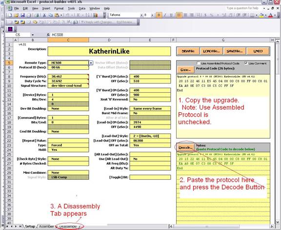
Using the generated protocol code is one of the easiest ways to get started with your assembly code. Fill in the timing data on the setup page. Make sure the “use assembled code” is unchecked.
- Copy the generated protocol code.
- Paste the protocol code into the decode area. As a best practice use “Paste Special Values” option from the menu, otherwise you may inadvertently paste protection into the cells.
- Press the Decode button and the Disassembly tab will appear.
You now have the starting assembly code for the selected processor.
Once you transfer the disassembly to the assembler tab you can add your own code. Its assumed that you have a working knowledge of the assembly language, and this document is just going to help you understand the PB interface.
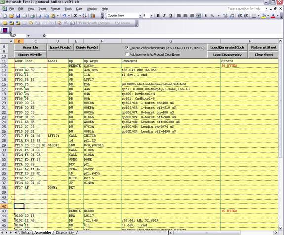
Below is a screen capture of the assembler tab. As with KM the pale yellow area indicates read-only areas. The dark yellow areas designed for user input except column H which is overwritten with the error code. Column B: is the address, and Column C: is the Object Code. Column D: is the Label, Column E is the Operator, Column F: is the Operator Arguments, Column G is the Comments and Column H: contains the error codes for the given line.
You may also notice that the example below shows the source code for two different remote classes, the s3c8+ and the HCS08.
In PB, the source code for the assembler is not case-sensitive, with one exception: literal quoted text strings used in a define-byte statement. White-space (spaces, etc.), unless part of a literal quoted text string, is ignored.
In general terms, the op code is entered in the Op column, and any arguments for the op code are entered in the OpArg column, with arguments separated by commas. Labels are entered in the Labels column. A colon may be entered after the label name, but is not required. Comments may be entered in the Comments column. No special syntax is required for comments, but a leading semicolon should be used if you expect to copy the code from Excel to a text file for use with another assembler. Column A is used for special purposes. The most common use for column A is to comment out an entire row by entering a semicolon.
Numeric values are interpreted as decimal by default. Hexadecimal values may be used, and can be indicated either with a leading '$' or trailing 'H'. Ex: $ABCD, ABCDH
For the S3C80 assembler, register references can be indicated with a leading 'R', and working registers indicated with a leading 'W'. Register references are always hexadecimal. Register-pair references using the 'RR' or 'WW' prefix are accepted, but not enforced.
For example (assuming RC0 is W0), these are all equivalent as far as the assembler is concerned: RC0, RRC0, W0, WW0.
Simple expressions may be used. The expression evaluator can only do addition, subtraction, multiplication and division, using the operators '+', '-', '*' and '/', respectively. Nesting with parenthesis is allowed. Results of an expression evaluation are truncated to an integer value.
Names of symbolic labels (and constants) must follow these rules:
- The first character must be a letter (A to Z)
- The remaining characters must be letters (A to Z), digits (0 to 9), or an underscore ('_').
- The name cannot evaluate to a hex value. For example, the name 'A001H' is invalid.
- For the S3C8 assembler, the name cannot look like a register reference. For example, 'R01' and 'W01' are invalid.
- Names are not case sensitive, so 'XYZ' is the same as 'xyz'
Assembly Tab User Interface
[Clear Sheet]
This button clears the Assembler sheet and sets the REMOTE directive on the first row to match the remote type selected on the Setup sheet. Any previously assembled binary code is erased.
[Load Generated Code]
This button clears the Assembler sheet and sets the REMOTE directive on the first row to match the remote type selected on the Setup sheet. The protocol code generated by the settings on the Setup sheet is then disassembled and placed on the Assembler sheet. Any previously assembled binary code is replaced by the generated code.
This makes it very convenient to use protocol-builder's Setup sheet to set the basic timing parameters as a starting point for creating a new protocol.
[Load Disassembly] button
This button is only enabled when the Disassembly sheet contains disassembled code that was obtained by using the [Decode] button on the Setup sheet. When used, this button clears the Assembler sheet and sets the REMOTE directive on the first row to match the remote type selected by the decoder. The disassembled protocol code is then placed on the Assembler sheet. Any previously assembled binary code is replaced by the decoded protocol code.
This makes it very convenient to use protocol-builder's decoder to disassemble an existing protocol for use as a starting point for modifying a protocol.
[Assemble] button
This button causes the assembler to execute and assemble the source code on the Assembler sheet. The assembler fills in the Addr and Code columns with the address and binary code respectively. If an error occurs on a row, the assembler will put an error message in the Errors column. On the row containing the REMOTE directive, the Errors column will be filled in either with the number of errors, or (if no errors) the number of bytes used by the protocol.
If the assembly completes with no errors, the resulting binary code is available for use on the Setup sheet. Checking the [Use Assembled Protocol Code] checkbox will cause the assembled code to be placed in the Protocol Code block instead of the normal PB-generated code.
Note that the assembled code is remote-type-specific, so only those remote types for which assembled code is available will be able to use the assembled code. If the assembled code has any errors, it will not be available. If required, PB can perform vector translation, vector offset or data offset processes on the assembled code before placing it in the Protocol Code block.
If source code for more than one type of remote is present on the Assembler sheet, the assembler processes all of them individually. An error in the source for one type of remote will not affect the assembly of source for other types. There can be only one set of source code for each of the five remote types.
[Use pre-defined constants] checkbox
If checked, then certain pre-defined constants are loaded prior to execution of the assembler. These constants are defined such that you can override them by redefining them in your source, if desired. Below is a list of the constants that will be defined and the values for each of the remote types.
                                     6805-
 Constant   HCS08  S3C8  S3C8+  SST  RC16/18 6805-C9  P8/740
 --------   -----  ----  -----  ---  ------- -------  ------
   DCBUF      $60   R03   R03   $5A     $5A     $5A      $5D
   PD00       $6A   R12   R12   $67     $67     $67      $6A
   PD01       $6B   R13   R13   $68     $68     $68      $6B
   PD02       $6C   R14   R14   $69     $69     $69      $6C
   PD03       $6D   R15   R15   $6A     $6A     $6A      $6D
   PD04       $6E   R16   R16   $6B     $6B     $6B      $6E
   PD05       $6F   R17   R17   $6C     $6C     $6C      $6F
   PD06       $70   R18   R18   $6D     $6D     $6D      $70
   PD07       $71   R19   R19   $6E     $6E     $6E      $71
   PD08       $72   R1A   R1A   $6F     $6F     $6F      $72
   PD09       $73   R1B   R1B   $70     $70     $70      $73
   PD0A       $74   R1C   R1C   $71     $71     $71      $74
   PD0B       $75   R1D   R1D   $72     $72     $72      $75
   PD0C       $76   R1E   R1E   $73     $73     $73      $76
   PD0D       $77   R1F   R1F   $74     $74     $74      $77
   PD0E       $78   R20   R20   $75     $75     $75      $78
   PD0F       $79   R21   R21   $76     $76     $76      $79
   PD10       $7A   R22   R22   $77     $77     $77      $7A
   PD11       $7B   R23   R23   $78     $78     $78      $7B
   PD12       $7C   R24   R24   $79     $79     $79      $7C
   PD13       $7D   R25   R25   $7A     $7A     $7A      $7D
   PD14       $7E   R26   R26   ---     ---     ---      ---
   PD15       $7F   R27   R27   ---     ---     ---      ---
   PD16       $80   ---   ---   ---     ---     ---      ---
   PD17       $81   ---   ---   ---     ---     ---      ---
   PD18       $82   ---   ---   ---     ---     ---      ---
   PD19       $83   ---   ---   ---     ---     ---      ---
   PD1A       $84   ---   ---   ---     ---     ---      ---
   PD1B       $85   ---   ---   ---     ---     ---      ---
   PD1C       $86   ---   ---   ---     ---     ---      ---
   PD1D       $87   ---   ---   ---     ---     ---      ---
   PD1E       $88   ---   ---   ---     ---     ---      ---
   PD1F       $89   ---   ---   ---     ---     ---      ---
   PF0        $A2   R28   R28   $7B     $7B     $7B      $7E
   PF1        $A3   R29   R29   $7C     $7C     $7C      $7F
   PF2        $A4   R2A   R2A   $7D     $7D     $7D      $80
   PF3        $A5   R2B   R2B   $7E     $7E     ---      $81
   PF4        $A6   R2C   R2C   $7F     $7F     ---      $82
   DBYTES     $A9   R10   R10   $66     $66     $66      $69
   CBYTES     $AA   R11   R11   ---     ---     ---      ---
   FLAGS      $B3   R00   R00   $57     $57     $57      $5A
   XMITIR   $FF5F $0133 $0146 $C02F   $01AF   $0183    $FF00
'---' above indicates the constant will not be defined.
The constant DCBUF refers to the first byte of the device-command buffer used during protocol execution, and is ten bytes long in all of the remote types. Other bytes within the buffer may be referenced with an offset notation, i.e., DCBUF+2 refers to the third byte in the buffer.
The constant DBYTES defines the address of the byte containing the number of device ("fixed") bytes within DCBUF. Similarly, CBYTES defines the address of the byte containing the number of command ("variable") bytes within DCBUF.
FLAGS defines the address of the byte that contains the bit-toggling bit(s).
The constant XMITIR is the address of the standard IR engine call for the remote.
[Add comments to Protocol Data Bytes] checkbox
If checked, then the next time the assembler is executed, it will replace any comments on rows defining protocol flag or data bytes with a description of what the values represent to the IR engine. This is only done if the assembly completes with no errors.
[Reformat Sheet] button
If, as a result of copying & pasting, etc. the format of the Assembler sheet gets corrupted, you can use this button to return the formatting to normal.
As distributed, the Assembler sheet is set to Protected mode. While most operations needed in creating source code can be performed with protection in effect, some functions are not available, such as search-and-replace. You are free to turn off the sheet protection (Tools menu, Protection, Unprotect Sheet) if you prefer, but be careful not to alter the contents of rows 1 through 9, and do not insert or delete any columns in the yellow area. (Rows 1 through 5 are hidden.) The Reformat Sheet button assumes that you have not inserted or deleted any of these rows.
[Insert Row] and [Delete Row] buttons
These buttons operate whether sheet Protection is in effect or not. The number of rows selected before clicking the button determines how many rows are inserted or deleted. Entire rows need not be selected; just selecting rows in one column will suffice. Only the yellow-colored columns will be affected, and selection of cells outside of the yellow areas will prevent the button from operating. No Undo is available after using these buttons.
Assembler directives
The assembler understands several special directives. These are listed below with a description of their use.
Remote
Each set of source code for a remote must begin with the REMOTE directive in the Op column, and a valid remote type in the OpArg column. The first row of the Assembler sheet will already have the REMOTE directive entered, and a drop list of valid remote types is available in the OpArg column. This information will have to be entered manually for any additional sets of source code.
Hint: Using the Alt-R key will enter the REMOTE directive on the current row (where cursor is), and create a droplist. Using Alt-R again will remove the droplist.
There can be only one set of source code for each of the seven remote types. If an invalid remote type is specified, the entire block of code (until the next REMOTE directive or the end of the source code is encountered) will not be assembled.
The valid remote types are:
- HCS08 - This selects the 68HCS08 assembler, and sets the starting assembly address to $0100. The resulting binary code is applicable to remotes using the HCS08 type on the Setup sheet.
- S3C8 - This selects the S3C80 assembler, and sets the starting assembly address to $8000. The resulting binary code is applicable to remotes using the S3C8 (Old) type on the Setup sheet. PB can also apply the vector translation process to make the assembled binary code available for use on S3C8 (New) remotes when S3C8+ code is not available.
- S3C8+ - This selects the S3C80 assembler, and sets the starting assembly address to $FF00. The resulting binary code is applicable to remotes using the S3C8 (New) type on the Setup sheet. PB can also apply the same type of vector translation used in KM & RM to make the assembled binary code available for use on S3C8 (Old) remotes.
- SST - This selects the 68HC05 assembler, and sets the starting assembly address to $0100. The resulting binary code is applicable to remotes using the SST type on the Setup sheet. PB can also apply a vector translation process to make the assembled binary code available for use on 6805-RC16/18 remotes when 6805-RC16/18 code is not available.
- 6805-RC16/18 - This selects the 68HC05 assembler, and sets the starting assembly address to $0100. The resulting binary code is applicable to remotes using the 6805-RC16/18 type on the Setup sheet. PB can also apply the same type of data and vector offsets used in KM & RM to make this binary code available for use on remotes with non-standard data or vector locations. The data locations must be manually indicated in the source by putting an underscore character in column A. PB can also apply a vector translation process to make the assembled binary code available for use on SST remotes when SST code is not available.
- 6805-C9 - This selects the 68HC05 assembler, and sets the starting assembly address to $0100. The resulting binary code is applicable to remotes using the 6805-C9 type on the Setup sheet.
- P8/740 - This selects the P8/740 assembler, and sets the starting assembly address to $0132. The resulting binary code is applicable to remotes using the P8/740 type on the Setup sheet.
- (NONE) - This disables assembly of the entire section. Since there can only be one active section for each remote type, this value may be used to deactivate different versions for the same remote type.
EQU (or EQ)
The EQU directive is used to define symbolic constants. The symbol name must be placed in the Label column, and must follow the naming rules for labels (see above). The OpArg column must contain an expression. The expression will be evaluated and the result assigned as the value of the symbol.
Seperate constants for hi-byte and lo-byte values must be defined in cases where the bytes of a 16-bit value need to be referenced in the source. (The expression evaluator is limited to basic add, subtract, multiply and divide operations, and cannot and, or, xor or shift.)
You can override the pre-defined constants added by the assembler when the checkbox option is active (see above) by redefining them in the source. Once defined in the source, you cannot redefine a constant a second time.
Symbolic constants and labels share the same namespace, so you may not use the same name for a label and a constant.
DB or BYTE
This directive generates binary output from one or more byte values supplied in the OpArg column. Each byte value must be separated with a comma. Examples:
DB $55,73H,27
Literal quoted text strings may also be defined with the DB or BYTE directive. The ASCII values of the text are output as byte values in the binary code.
DB "Text string"
DW or WORD
This directive generates binary output from one or more 16-bit word values supplied in the OpArg column. Each word value must be separated with a comma. Examples:
DW $5555,7373H,65530
Note that the HCS08, S3C80 and 68HC05 assemblers output word values in high-byte, low byte order, wheras the P8/740 assembler outputs word values in the opposite order. Use caution when using words to define protocol data values with the P8/740 assembler; it may be best to use byte definitions to prevent errors.
XORG
The XORG directive sets the target location counter. The OpArg column must contain an expression.
Initially, the target location counter is the same as the current location counter. The XORG directive is useful when writing code that will be executed at a different address than the assembled code. While generally not used in writing protocols, it might be useful to authors of special protocols to be used with extenders.
The target location counter affects calculation of relative branches, and values of labels.
The target location counter may be restored to match the current location counter by setting it to '.'. (The dot special symbol returns the value of the current location counter.)
WREG, WREGL and WREGH
These directives are only valid for the S3C80 assembler. The OpArg column must contain an expression, or the special arguments ON or OFF.
The WREG directives used with an expression argument tell the assembler which registers are to be used as the working registers for purposes of assembling the code. WREG sets both the low and high working registers, while WREGL and WREGH set the low and high registers separately. The assembler will accept any values from 0 to $F0 ($F8 for WREGL & WREGH) where the lower three bits are zero. At the start of assembly, the initial setting of the working registers is equivalent to WREG $C0.
The assembler will use the working register setting to automatically convert register references to working register references. For some instructions, there are forms that will accept either normal register references or working register references, with the latter using fewer bytes in the instruction, and usually executing faster. In cases where you want to use the longer instruction form, you will need to use the WREG special argument OFF. The assembler will then not allow any working register conversion for those instructions. To return the assembler to normal, use the WREG special argument ON.
For example, with the default settings (WREG set to ON and WREG set to $C0), the following are all equivalent, and produce the same binary code:
     =00C0    SYMB1   EQU   C0H
     09 01            LD    R01,W0
     09 01            LD    R01,RC0
     09 01            LD    R01,C0H
     09 01            LD    R01,SYMB1
With WREG set to OFF, the same source produces the longer form of the instruction:
     =00C0    SYMB1   EQU   C0H
                      WREG  OFF
     E4 C0 01         LD    R01,W0
     E4 C0 01         LD    R01,RC0
     E4 C0 01         LD    R01,C0H
     E4 C0 01         LD    R01,SYMB1
                      WREG  ON
Some or all of the address modes of the following instructions are affected by the WREG ON/OFF setting:
LD, INC, ADC, ADD, AND, CP, OR, SBC, SUB, TCM, TM, XOR
OTHER/MISCELLANEOUS
The '.' symbol The dot ('.') symbol returns the value of the current location counter. The current location counter specifies the address at which the instruction/data bytes will reside. You may use the dot in any expression. For example, the following code jumps to the branch instruction in an endless loop:
     JR    .   (S3C80)
     BRA   .   (HCS08, 68HC05 & P8/740)
Column A Column A of the Assembler sheet is used for special purposes. Below are the currently available uses for this column.
- A semicolon (;) anywhere in the text in column A will cause the entire row to be treated as a comment. This is useful if you are trying several different approaches and want to retain the source code for other approaches for reference while developing a new approach.
- Under some circumstances, protocol binaries are subjected to a vector translation or vector offset process. Calls and Jumps to certain addresses are altered to refer to different addresses in this process. While it is unlikely, it is possible that data bytes or other code within the protocol might appear to be a call or jump instruction. If this occurs, you can flag a specific row so that it cannot be considered for this process by putting a dot in column A. This will cause a dot to be used as a delimiter between the bytes in the code column, which will prevent the vector translation/offset process from changing those bytes. The dot is only effective if more than one byte is generated on the row where it is used. Code exported to KM or RM (see below) will also contain the dot.
- Under some circumstances, protocol binaries need to be subjected to a data offset process. References to certain data addresses are then altered to refer to different addresses in this process. At this time, only the 6805-RC16/18 remote types require this. References to the protocol data (PDxx) and protocol flag (PFx) bytes must be flagged with an underscore in column A to allow this process to recognize the references. This will cause an underscore to be used as a delimiter between the bytes in the code column. Code exported to KM or RM (see below) will also contain the underscore.
Adding to Keymap Master (KM)
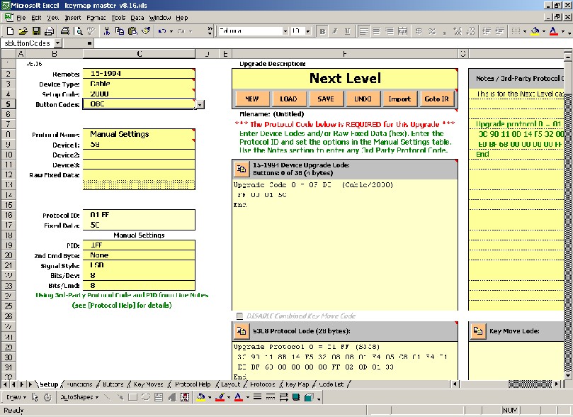
In KM, you should select "Manual Settings" as the protocol and you should cut & paste the protocol code generated by PB into the Notes panel. (You can still enter notes there too, if you like, KM will find the protocol). You should also select OBC for the button codes.
When you select "Manual Settings" a new set of options appears in the lower left hand side of the screen.
PID: this is the protocol id that you used in PB. 2nd Cmd Byte: this is only relevant for signals with more than 1 byte of variable data. Signal Style: Sometimes this one is a crap-shoot. Take a look at the binary signals shown in the codes3.txt file. Ideally, you would notice that the numbers increase from the left (LSB) or the right (MSB) when you’re looking at the data for the numeric buttons, but that's not exactly the case here. However, you should notice that the last 2 bits on the right stay constant whereas the bits on the left change constantly, therefore I'm going to make the call that this protocol is LSB. Use of one of the -COMP styles implies that you got the ‘1’ and '0' pairs reversed, which is not typically the case for a protocol that you created yourself. Bits/Dev: this should match what you selected in PB. Bits/Cmd: this should match what you selected in PB.
So far, so good, but now you need to enter the functions and their OBCs in the Functions sheet, so you need to figure out what they are, and you still need to figure out what to enter as the device code for this upgrade.
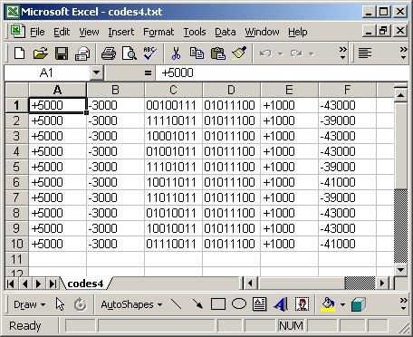
codes4.txt (from the zip file) is a cleaned up version of codes3.txt with just one line per signal. You should open this file using Excel. Select "fixed width" and make sure all the columns are treated as text. You should end up with a sheet that looks like this...
The first two columns show the lead in times and the last two show the lead out times, so you can delete those. As we determined that the signal style is LSB, in order to convert the binary signals to decimal, we will need to read them backwards. The easiest way to reverse the order of binary patterns in Excel is to use the MID function. The following formula would reverse the order of an 8 bit binary pattern in cell A1:
= mid(a1,8,1)& mid(a1,7,1)& mid(a1,6,1)& mid(a1,5,1)& mid(a1,4,1)& mid(a1,3,1)& mid(a1,2,1)& mid(a1,1,1)
Assuming that the two columns of binary are now in columns A and B, you could enter this foruma in column C and then copy it to column D, which would give you two columns of binary where the data from columns A and B are reversed.
You could then use the following formula in column E to convert the command codes to decimal:
=bin2dec(c1)
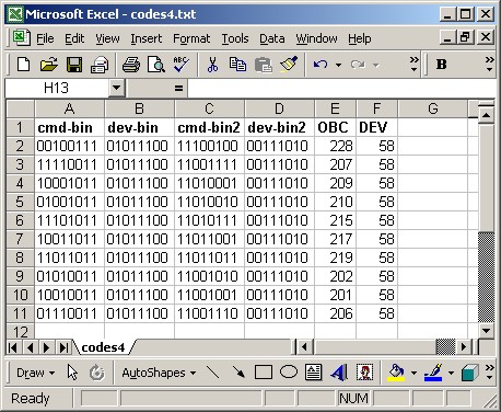
You could then copy this formula to column F in order for it to convert the device codes to decimal. You should end up with a sheet that looks like this (I added column headings to help illustrate the fields). (I have included this spreadsheet in the zip file, it’s called codes4.xls)
Therefore, the device code for our upgrade is 58, and the OBCs for the numeric buttons are as shown.
The Setup sheet in KM should look like this...
Adding to Remote Master (RM)
There are several ways to get a custom protocol into a RM.
You can create a custom protocols.ini entry, but if the official JP1 protocols.ini is not changed, the RDMU file will be unusable by the rest of the community. If you have Microsoft Excel you can create a KM upgrade and then open it in RM. You can also create a self-contained RDMU with a custom protocol. If you have Excel it is recommended that you create a KM sheet because it can be accessed by both KM and RM, but there are still advantages to doing development work in RM . RM lets you work directly with the hex, which can do the OBC and EFC calculations for you.
In this document we are going to show you how to create a self-contained RDMU file. It is an easy process but not intuitive.
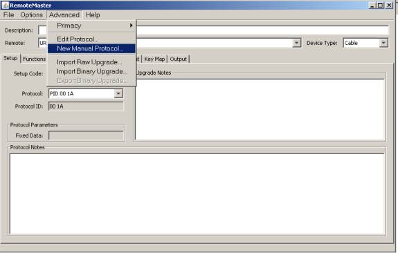
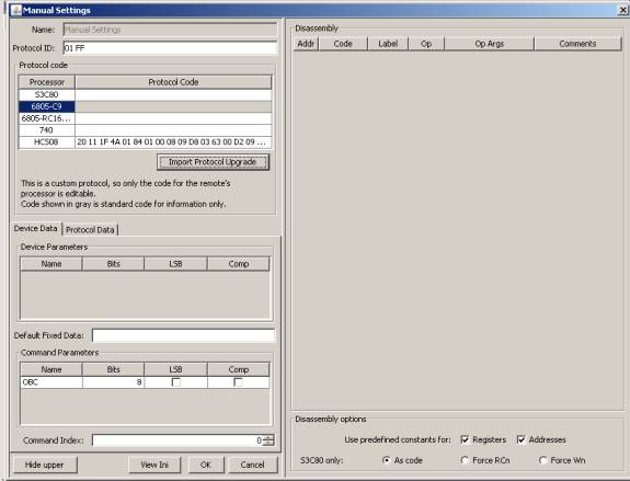
In RM, you begin by accessing the New Manual Protocol option from the Advanced Menu. This was known as the “Manual Protocol” option in earlier versions of RM. In RMIR, after a remote image has been loaded (by opening a *.RMIR or *.IR file, downloading from a remote, or by File\New\RemoteImage), use the Protocols tab and click New.
In RM 2.02 Alpha 10a, when the manual settings screen comes up, the “Import Protocol Upgrade” is not enabled until you touch the Protocol Code box.
Pressing the Import Protocol Upgrade button will import a formatted protocol that was copied to the clipboard in PB. In this case the clipboard contained this protocol from PB.
Upgrade protocol 0 = 01 FF (HCS08) Dimmer (PB v4.01)
   20 11 1F 4A 01 84 01 00 08 09 D8 03 63 00 D2 09
   F3 41 D2 CC FF 5F
End
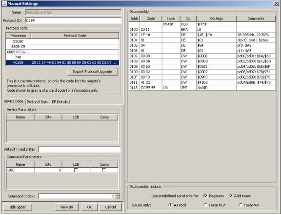
RM analyzes the protocol, finds the protocol ID to be 01FF and the processor type to be HCS08 and inserts it into the proper protocol code area. RM also analyzes the protocol to see how many device and function bytes are called for.
Note: If the protocol code next to any given processor is enabled (black instead of gray), you can manipulate the protocol bytes directly by double clicking on protocol code.
If you click on the HCS08, you can see the disassembly for the protocol upgrade in the right hand panel. A quick glance at the disassembly can be helpful in making sure that you had the correct data on the clipboard.
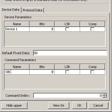
In the lower left corner of the manual settings page there will be an area where you can tell RM how to handle data. This area will look different depending on the protocol that you imported. You can tell RM if the data is LSB- Least significant bit first. You can tell RM whether the data needs to be Comp (complemented 0 is 1 and 1 is 0). Although the number of bits per devices and commands have already been specified in PB, the user can overide this if a complex protocol needs to perform some bit manipulation from within the executor. If the protocol requires multiple bytes per function, you can specify the command index, which tells RM whether the OBC portion is the first hex byte or the second hex byte.
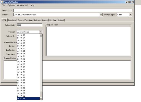
Once the protocol settings are complete, click OK. You must now change the PID on the Setup tab to match your protocol update. (If using RMIR, first change to the Devices tab, and click New.) It will be at the bottom of the protocol list. The code will only appear on the list if a protocol has been entered for the processor type of the chosen remote.
Note: The custom protocol MUST be selected on the Setup tab before you can make any changes to the custom protocol's manual settings.
To revisit the manual settings page, click Advanced\Edit Protocol. This will open the protocol currently selected on the Setup tab, so be sure your custom protocol is selected. (In RMIR, if an upgrade is using the custom protocol, click the protocol name or PID on the Devices tab.)
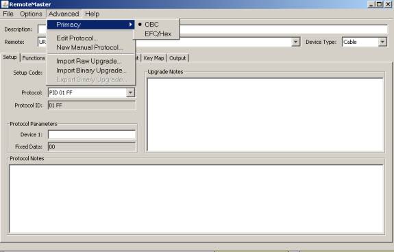
If you have already worked on the function page and then realize you need to make corrections to the Manual Settings Page, it is important that you check your “Primacy” settings before making the changes, so that you don’t corrupt all your data. Any changes to LSB, Comp, # of bits or Command Index will change the way calculations are performed. The Primacy setting lets you determine whether you want the OBC or EFC/Hex to be preserved when you change the calculation method. The Primacy setting is found in the Advanced Menu in RM, as shown below.
So far, so good, but now you need to enter the functions in the Functions sheet, so you need to figure out what they are. You can calculate the OBC's or you can enter the hex that you need and let RM compute the OBC's.
