Infrared Protocol Primer
by Vicky G (available as a PDF here)
Infrared signals are often described with numbers or IRP notation. I have been intrigued by the decoding process. I have diligently worked the examples, and asked questions, that were patiently answered. But I didn’t understand. It was all too abstract for me. When I started using Kevin Timmerman’s IRScope software with the Widget that I purchased from Tommy Tyler, I was finally able to understand what I was reading. Seeing the graphical representation of the numbers and the terms finally helped me to see what was going on.
If you’ve been having trouble with the terminology and trouble understanding the raw timings and the IRP notation, read further.
Infrared protocols have distinctive characteristics. They can be distinguished from one another by things like repeat style, frequency, lead-in style, lead-out style, timing pairs, encoding method and rules for data integrity.
Repeating
Infrared signals are divided up into frames. We need to look at several frames of data to see how repeating occurs. That is why the proper way to learn signals is to hold the sending button down until the learning is complete. Some protocols have a "break" frame, so on occasion it's necessary to use a different technique where you release the sending button before the learning process has completed, in order to capture the last frame.
Here are two different types of NEC signals. The first is a NEC1, the second is a NEC2. Just by glancing at that picture we can see they are different. They have different repeating styles.
The NEC2 signal resends the whole signal while the button is held, the NEC1 signal only sends this information ![]() after the first frame. For NEC1 equipment, that simple repeating frame is enough to get functions like VOL+ to repeat. Using the NEC2 on NEC1 equipment is likely to give extra repeats on keys that don’t normally repeat when held, like your numbers. If you use NEC1 when a NEC2 is required, it will cause the keys that you should repeat when held, like vol+ and vol-, not to repeat at all.
after the first frame. For NEC1 equipment, that simple repeating frame is enough to get functions like VOL+ to repeat. Using the NEC2 on NEC1 equipment is likely to give extra repeats on keys that don’t normally repeat when held, like your numbers. If you use NEC1 when a NEC2 is required, it will cause the keys that you should repeat when held, like vol+ and vol-, not to repeat at all.
Timings
So how is this to reduced to a bunch of numbers? Well let’ zoom in on these NEC signals a little closer.

The numbers under the line represent the amount of time that has passed. Note these are all really positive numbers, but we show them with a + and – to help visualize the signal. The + shows an infrared pulse, the – shows quiet time. This would be shown as
+8830 –4396 +579 –1621 +579 –1646 +554 –1646 +554 –546 +554 –546 +554 –546 +554 –546 +554 –546 +554 –1646
+579 –1621 +579 –1621 +579 –521 +579 –547 +553 –547 +553 –547 +553  -547 +553 –1647 +553 –547 +553 –1647
+576 –524 +576 –524 +576 –524 +576 –524 +576 –524 +576 -524 +576 –1624 +576 -524 +576 –1650 +550 –1650
+550 –1650 +550 –1650 +576 –1624 +576 –41347 +8830
Rounding
The timings that DecodeIR uses for decoding come from a wide variety of sources. The accuracy of the timings will vary depending on the equipment that was used to collect them. These timings need to rounded. In our example here, the smaller pulses have values of +550 +553 +554 + 576 +579. Differences that small are insignificant in most IR protocols. All of these pulse widths should be considered to be equal, and rounded to the same value. Picking a good rounding number will vary based on the data on hand, but in the case of an NEC signal, 550 would be a good number to round to. Sometimes a smaller number is better (eg, 10 or 100). The idea is to get all timings that basically represent the same time, to get rounded to the same value. In this case, if some times where 538 and others were 578, rounding to 100 would not be ideal because they'd round to 500 and 600 respectively.
+8800 –4400 +550 –1650 +550 –1650 +550 –1650 +550 –550 +550 –550 +550 –550 +550 –550 +550 –550 +550 –1650
+550 –1650 +550 –1650 +550 –550 +550 –550 +550 –550 +550 –550 +550  -550 +550 –1650 +550 –550 +550 –1650
+550 –550 +550 –550 +550 –550 +550 –550 +550 –550 +550 -550 +550 –1650 +550 -550 +550 –1650 +550 –1650
+550 –1650 +550 –1650 +550 –1650 +550 –41250
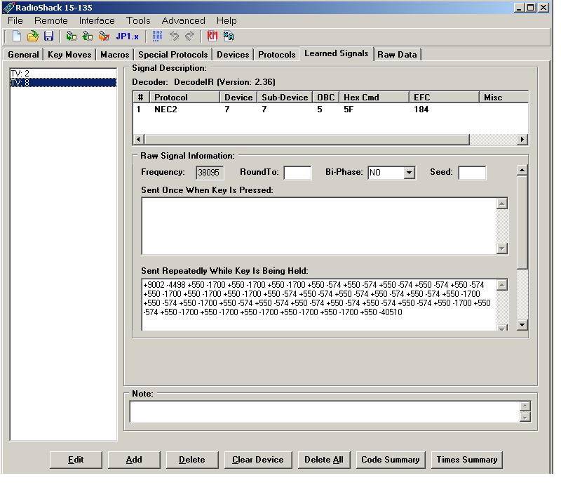
I captured these same signals to one of my remotes and looked at them in IR. If you want to see the raw signal information in IR.EXE on all learns, even those learns that decoded, you need to turn on Adavanced/Forced Learned Timings option in the menus. This option is off by default. When I looked at the learns in IR, the values were much different than the timings I caught on my widget, and yet DecodeIR decoded them to the same NEC signal.
Remember that the NEC2 signal keeps sending the whole signal as it repeats, so there is nothing in the “sent once when the key is pressed:” window.
![]()
NOTE: The [Code Summary] and [Times Summary] buttons will be available in IR 8.01 and later.
In contrast, the NEC1 sends different information when its repeats, so the raw timings would look different.
![]()
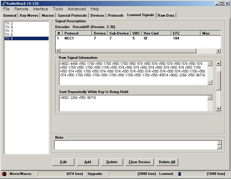
The ”Sent Repeatedly While Pressed:” window shows a numerical representation of the second and third frames shown in our diagram.
Frequency
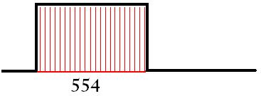
Another of the characteristics that defines a protocol is its frequency. So what is happening frequently? Those little bumps or pulses in the signal were not actually solid, but rather made up of little infrared flashes. My scope saw 22 infrared flashes during the 554u seconds of this pulse. Sometimes during decoding, the frequency is the only thing that distinguishes one protocol from another. For example Pioneer protocol looks just like the NEC protocol, except the Pioneer’s frequency is 40kHz, while the NEC has a frequency of 38kHz.
Duty Cycle
I want to take a moment to discuss duty cycle. Technically the duty cycle does not belong here. It is not a part of the protocol. You won’t see the duty cycle in IRP notation nor in the timing data. However when you use Protocol Builder to build your first protocol, the second field asks for a duty cycle, so I thought I’d describe it here. Duty cycles are related to these infrared flashes that make up the pulse. The duty cycle is the percentage of time the flashes are lit.
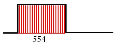
This diagram depicts a higher duty cycle than duty cycle in the diagram above.
Unless you have a good reason to do otherwise, you can always just set the duty cycle to 33%. Setting it to a higher value (like 50%) may produce a stronger signal but will also run the batteries down quicker.
Structure
If you look at our NEC signals you can see a big pulse of infrared activity at the beginning, followed by a big silence. If your signal contains this kind of structure it has a lead-in pair. Not all protocols use a lead-in pair. That long period of silence before the repeats start is called the lead-out time. The area between our lead-in pair, and lead-out time is where the actual data resides.
Lead-In Pair
So the first thing we’re going to do on decoding a signal is see if it has a lead-in pair. Here are some simple signals where you can look to see if there is a lead-in time or not.
Lead-Out Time
After the signal is sent there will be a large period of silence called the lead-out time. Lead-out times can be just a period of silence or they can add a pulse or two.
With the lead-out OneOn Pulse, an extra one on pulse is generated.
Lead-out times can be a constant or a variable.
In IRP the timeouts would be shown
-40000 would be a constant timeout,
^108000 would show that each frame needed to be the same length
Midframe Burst
 A mid-frame burst is a timing pair that is not either the ONE pair or the ZERO pair and it appears somewhere in the middle of the data string. There are 2 types of mid-frame burst pairs supported by UEI's IR engine, but only a mid-frame burst with a one-on-pulse followed by the silence that is equal to the lead-in silence, like the one above, can be created in protocol builder without additional assembly code.
Timing Pair
A timing pair is comprised of two times, the pulse and the silence time. Did you notice that I’ve been calling those bumps, pulses instead of ON times. I have done that purposefully so that you don’t do the whole on = 1 off = 0 thing that I did. That is WRONG. Decodes interpret the data portion of a signal into 0’s and 1’s, but its done with a timing pair.
Decoding is done frame by frame. Structural parts of the signal like lead-in pairs, lead-out times and mid-frame bursts are not a part of the data portion of the signal, so they are ignored when decoding our data into 0’s and 1’s..
There are several encoding systems. The most common IR encoding methods are pulse width and phase encoding. A determination needs to be made as to whether the bumps on our line can be interpreted with a pulse width method, or if they are phase encoded.
Pulse Width Timing Pairs
These are the timing pairs for the signal above.
+550, -550,  +550, -1650,  +550, -550, +550, -1650, +550, -1650, +550, -1650,
+550, -1650, +550, -1650, +550, -1650, +550, -550, +550, -1650, +550, -1650,
+550, -1650, +550, -1650, +550-1650, +550,?
We had to do some rounding to get the numbers to look so nice. You can see we have 2 timing pairs.
0 = 550,-550
1 = 550,-1650
If protocols use the pulse width method, each bit will start with a pulse, followed by a period of silence.
In IRP Notation this could be written as :
<550,-550| 550,-1650> meaning each 0 bit is represented by durations of 550,-550 and each 1 bit by durations of 550,-1650.
Or since these numbers are all divisible by 550, this would more often be written as
{550} <1,-1|1,-3>
Phase Encoded Timing Pairs
Remember that our pulse width signal is defined by a pulse followed by a silence, no matter if it was a one or a zero. In a phase encoded protocol the silence and pulse parts change order.
Whenever you see the data portion of the signal with 2 or 3 different pulse widths AND 2 or 3 different silence widths, you need to determine if the raw timings are phase encoded, or pulse width encoded with these tests..
The widest pulse = "0 pulse width" + "1 pulse width"
The widest silence = "0 silence width" + "1 silence width"
Data portion of different signals would show different number of bits if you tried to decode it with the pulse width method.
When there are only 2 values for the pulse and silence widths we’ll assume that the "0 pulse width" = the "1 pulse width").
This is a phase encoded signal, the timings widths are shown below.
-500, +500, -500, + 1000, -500, +500, -500, +500, -500, +500, -500, +500, -500, +500, -500, +500,
-500, +500, -500, +500, -500, +500, -500, +500, -1000 +500,
On inspection we see two widths for both pulses (+500 and +1000) and silences (-500 and -1000), so we are going to test this to see if its phase encoded .
+1000 = +500 + +500 	(passed this test)
-1000 = -500 + -500	(passed this test)
So this might be phase encoded, depending on how different button presses decoded under the pulse phase method.
This was indeed a phase encoded signal, and
0 = +500, -500
1 = -500, +500
In IRP Notation this could be written as
<+500,-500|-500,+500>
meaning that 0 bit is represented by durations of +500,-500 and a 1 by –500,+500
Or since these numbers are all divisible by 500 this would more often be written as
{500} <|1,-1|-1,+1>
If you are working from learns from a remote, IR.exe makes this easy. IR.exe can to check for bi-phase using the Bi-Phase drop down, and +1000 and – 1000 widths would be as shown as +500, +500 and –500, -500 in the raw data.
IRP
Besides the frequency, lead-in pair, lead-in style, lead-out style, and timing pairs, signals may also follow a bunch of rules for data integrity like parity, checksums and complements. A good way to learn how to decode unknown protocols is to know how known protocols are constructed. Many are documented in the DecodeIR.HTM that John Fine packages with his DecodeIR.DLL.
The catch-22 for me, was that to understand the IRP, you had to have a basic understanding of how signals looked.
Boolean Operators
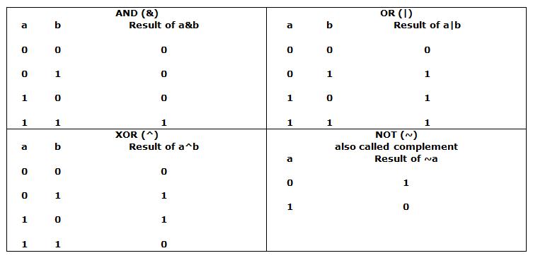
First of all I was unfamiliar with the Boolean symbols that were being used. I’d never seen them before I encountered them in IRP. I thought they were something unique to IRP until I encountered them when I was reading about C++.
These operators (^ and ~ & and ! ) will often used in the formulas that insure data integrity.
Units
- Numbers in IRP will use k, u and m.
- 38k = 38 kilohertz or 38000 Hz
- 500u = 500 microseconds
- 100m = 100 milliseconds, which would be 100000u
{} – Timing Data, and orientation
- These {} may include 3 pieces of information. I
- multiplier - optional, a multiplier or modulus for the timing pairs
- frequency - a number followed by a k gives the frequency.
- orientation - You may see lsb, msb. If this entry is not present, the signal is read as lsb for decoding( least significant bit first). I had thought this only applied to official protocols. I couldn’t imagine why anyone would choose to read the numbers backwards, but it turns out that we want to use lsb if it makes our OBC’s make sense.
<ZerosTimingPair | OnesTtimingPair> - Timing Pairs
The <> will show pairs of positive and negative numbers separated by a |. There will be at least 1 pair, but there can be more pairs on a very complicated signal. If there was a multiplier in the {} brackets, then these numbers need to be multiplied to see the actual pulse and silence times being sent. If these numbers appear with a “u” like 425u, then they will not be multiplied by the multiplier that is seen in the {} brackets.
- <+1,-1|+1,-3> pulse width encoded timings
- <+1,-1|-1,+1> phase encoded timing pair
(item1, item2, item3, item4………. ) – Signal makeup
Signals are made up of two type items, structural timings items that are inherent to the protocol, and data items. Structural items include things that do not convey data, like lead-in pulses, lead-in silences, lead-out times…..
Structural timing items
- +number defines a pulse
- +1 - a pulse that uses a multiplier to get the time in microseconds
- +250u - a pulse that wasn’t divisible by the multiplier so its specified in microseconds
- -number defines a silence
- -3 - a silence that uses a multiplier to get the time in microseconds
- -445u - a silence that is already specified in microseconds
Data items
- Expression:Number of bits
- Expression could be a constant
- 32:8 - Value 32 in 8 bits
- Expression could be a variable
- Variable are shown as capital letters. Some variable have special meaning.
- D := device
- S := subdevice
- F := function which we call and OBC in JP1 land
- T := toggle. Toggles are bits that change.
- D:5 5 bit device
- Variable are shown as capital letters. Some variable have special meaning.
- Expression could be a constant
- Expression could be a formula
- ~D:5 complement of the device shown in next
- D^F:8 D xor F in the next 8 bits
- Expression could be a formula
- Expression:Number of bits:Starting with bit
- F:4:2 the next 4 bits would start with bit 2 of F. The value after the second : is the number of bits skipped to reach the field. This is always relative to the LSB end of the value, even in MSB signals. So working from the LSB end, of ~F, we skip 2 bits and then select the next 4 bits.
- Expression:Number of bits:Starting with bit
Repeating
In IRP when items in parenthesis are followed with a + or * it means they repeat.
- The * means it repeats zero or more times. So for a very short button press the part in () might be skipped entirely.
- The + means it repeats one or more times.
Let's look at the IRP for the two NEC signals.
| {38.4k,564} | Frequency = 38,400Hz, Multiplier = 564 for the times. protocol is lsb| | |
| 1,-3> | 0 = +564,-564 1 = +564,-1622 |
because we used the 564 multiplier signal is pulse encoded because both pairs end with – value |
| (16, -8 | pulse of 9024 followed by 4512uS of silence | |
| D:8,S:8,F8,~F:8 | this is the data portion of our signal first 8 bits is going to be the device second 8 bits is going to be the subdevice next 8 bits is the function next 8 bits will be the complement of the function if the data had been 00000111 00000111 00000101 111111010 we would have known device = 7, subdevice = 7, f= 5 because this is an lsb protocol and has to be read backwards | |
| 1,-78 | pulse of 564uS silence of 43992uS | |
| )+ | the + shows that everything in the parentheses repeats one or more times | |
| {38.4k,564} | same as NEC2 |
| 1,-3> | same as NEC2 |
| (16,-8, | same as NEC2 |
| D:8,S:8,F:8,~F:8, | same as NEC2 |
| 1,-78, | same as NEC2 |
| (16,-4, | pulse of 9024us silence of 2256us (note this is half the size of the silence in the first frame |
| 1,-173)*) | pulse on of 564us pulse off of 97522uS |
| )*) | the * means the part in the inner parenthesis repeats 0 or more times |
Alternate Lead-Out
![]() The NEC1 lead-out times could have been shown like this as well.
NEC1
The NEC1 lead-out times could have been shown like this as well.
NEC1
IRP notation: {38.4k,564}<1,-1|1,-3>(16,-8,D:8,S:8,F:8,~F:8,1,-78,(16,-4,1,-173)*)
IRP notation: {38.4k,564}<1,-1|1,-3>(16,-8,D:8,S:8,F:8,~F:8,1,^108m,(16,-4,1,^108m)*)
As you can see, each frame in our NEC1 signal is the same width. If we added up all the widths of all the pulses and silences we would come up with 108348u which would be rounded to 108m. Specifying the timeout as ^108m makes it easier to see that these signals are going to be equal frame length, instead of seeing the –78 and –173.

