I have plans to come up with a combo device (http://www.hifi-remote.com/forums/viewt ... 186#107186) and that requires me to understand how the tools we use work.
I believe a good warm up exercise would be to start off by building my own cable!
Referring to the "Schematic of JP1X interface" (last page of "New Interface Designs.pdf" hosted in http://www.hifi-remote.com/forums/dload ... le_id=5975), I see that the RS232 signals have been inverted through open drain not gates and then connected to the remote's controller.
The RS232 signals by design "comes out" inverted in polarity though, so if I were to use a USB<->Serial cable, would I need to have the open drain not gates betwwen the cable and the remote as well?
This USB<->Serial cable talks 5v and 3v3 though - not RS232 levels.
The USB<->Serial cable I intend to use is like the one described here: http://jimlaurwilliams.org/wordpress/?p=999
More specifically:
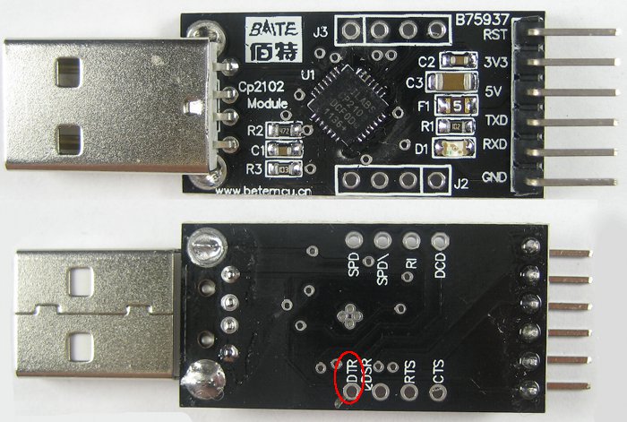
If my understanding is correct, all I would have to do is connect the pins from this adapter to the 2x3 pin port of my remote, with my remote powered on, without the need of the intermediate gates?