Dear All,
I found a Silabs CP2101 IC at home, and decided to build a JP1 interface around it.
http://www.silabs.com/Support%20Documen ... CP2101.pdf
I found the following lines:
CP2101 Pin 3 -> JP1 Pin 3 (GND)
CP2101 Pin 26 -> JP1 Pin 4 (TXD)
CP2101 Pin 25 -> JP1 Pin 6 (RXD)
But I don't know where to connect the JP1 Pin 2 (reset) line. My guess is the Pin 24 (RTS), but I'm not sure if it's inverted or not...
Could you please somebody help me?
Thank you in advance,
TiceRex
Silabs CP2101
Moderator: Moderators
The interface cable I built is partially working.
When I plug it into the remote it blinks twice. I started the jp1xtest program, after a few seconds the remote blinks twice again, and then the program says: no jp1 remote found.
It seems that the remote is found by the test program, but cannot initialize the programming mode.
Could anybody help me please? What could be wrong?
What pin did you end up using? RTS(pin24) or DTR(pin28) to IDC pin2?
The Double blink LED looks like the /RESET(IDC pin2) is working though. Maybe you have RX/TX reversed but your description looks correct. IDC pin4 is DataIn and IDC pin6 is DataOut.
BaudRate is 38400 8N1. I don't know what equipment you have around but you may want to validate with a known 38400 8N1 source.
I believe Tommy had a guide on troubleshooting JP1.X interfaces.
I tried both RTS and DTR lines, with logic high and logic low (configurable on the chip). Also tried reversing RXD and TXD, without any success. I went through the troubleshooting guide, but everything shows the cable should work properly.
However, according to the debug tester there's no answer from the remote:
I think I should read a little bit more about serial communications before starting such a project... 
However, according to the debug tester there's no answer from the remote:
Code: Select all
Opening COM5
DCB paramaters:
  DCBlength=28
  BaudRate=38400
  fBinary=1
  fParity=0
  fOutxCtsFlow=0
  fOutxDsrFlow=0
  fDtrControl=0
  fDsrSensitivity=0
  fTXContinueOnXoff=0
  fOutX=0
  fInX=0
  fErrorChar=0
  fNull=0
  fRtsControl=0
  fAbortOnError=0
  fDummy2=0
  wReserved=0
  XonLim=32768
  XoffLim=8192
  ByteSize=8
  Parity=0
  StopBits=0
  XonChar=17
  XoffChar=19
  ErrorChar=0
  EofChar=0
  EvtChar=0
  wReserved1=0
CLRRTS
CLRDTR
SETDTR
SETBREAK
CLRBREAK
Purging RX and TX buffers
Reading up to 20 bytes to flush out spurious data
Didn't get any spurious data
Sending tEst command (45h)
Reading up to 20 bytes of response
Got no response
CLRDTR
SETDTR
SETRTS
CLRRTS
Purging RX and TX buffers
Reading up to 20 bytes to flush out spurious data
Didn't get any spurious data
Sending tEst command (45h)
Reading up to 20 bytes of response
Got no response
SETBREAK
SETRTS
CLRRTS
CLRBREAK
Purging RX and TX buffers
Reading up to 20 bytes to flush out spurious data
Didn't get any spurious data
Sending tEst command (45h)
Reading up to 20 bytes of response
Got no response
Opening COM6
Yes, the CP2101 driver is working and is tied to COM5. What I'm not sure about is the flow control (XOn/XOff, Hardware, None) and UART (FIFO Buffer) settings...
The remotes are URC7950 (3029) and URC8350 (1169), both working properly via another (serial) cable.
But never mind, I think I will give it up and throw this crippled IC to trash. I've ordered an FTDI 232R cable, which has much better support and proven record to work. Experimenting with CP2101 was just a challenge.
Hi,
I had similar experience. Compounded by not realising my one remote was a JP1.4 and the other remote has a partially scrambled program so not sure if it is working.
I have recorded most of my experiments in the post at
http://www.hifi-remote.com/forums/viewt ... p?p=102940
One thing that was interesting was that the CP2101 USB-TTL converter does work with the JP1.4 remote test software. When doing the manual tests it works on the JP1.3 but the applications do not see the remote.
There is obviously some quirk in the IC that makes it not quite 100% compatible with the authentic 82550 UART chip and the FTDI chips seem to have the best reputaion for working with strange software. All the converters work fine for simple asynchronous commnications, it is the subtle functions of the interface that are not fully implemented.
Kalle
--
Johannesburg, South Africa
Kalle Pihlajasaari
Lahti, Finland
Lahti, Finland
Flow control is None as far as I know. I don't recall having to set any UART buffer settings.TiceRex wrote:Yes, the CP2101 driver is working and is tied to COM5. What I'm not sure about is the flow control (XOn/XOff, Hardware, None) and UART (FIFO Buffer) settings...
The remotes are URC7950 (3029) and URC8350 (1169), both working properly via another (serial) cable.
But never mind, I think I will give it up and throw this crippled IC to trash. I've ordered an FTDI 232R cable, which has much better support and proven record to work. Experimenting with CP2101 was just a challenge.
Perhaps if you are curious, you can use the other working cable to validate parts of the non-working cable. KalleP's thread had some good suggestions of trying to validate the RESET function and then using the working cable to snoop the data using realterm program on the TX/RX lines to make sure you see the correct bytes crossing.
To see all the data as 00's suggests the TTL voltage levels may not be correct and the chip is sampling the level as a "zero". It could also mean the remote has not been RESET correctly and is not ready for the JP1.X communication protocol.
-
Kevin Timmerman
- Expert
- Posts: 142
- Joined: Tue Jan 09, 2007 5:52 pm
- Location: West Michigan
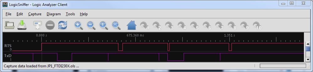
The JP1.1, 1.2 and 1.3 remotes require the TxD line to be held in a break state during initialization of communication. Here is a logic analyzer capture of a FT230X chip beginning JP1.x communication. Note the two ~100 ms break conditions.
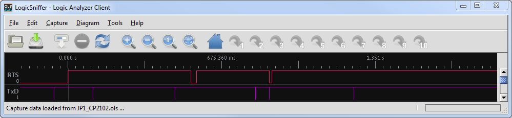
Here is the same for the SiLabs CP2102. Note that the 100 ms breaks are missing and there is just a brief pulse of the TxD line instead.
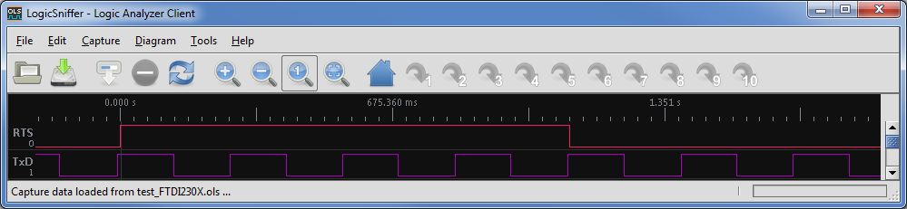
That could be some quirk of the JP1 DLL, so I used a simple test program to toggle TxD, DTR. and RTS in a 1:2:4 ratio. Here is the FT230X chip. It works as expected. The TxD line toggles at 4 times the rate of RTS.
The CP2102 chips fails this test. Again there is just a brief pulse instead of a break state.

SiLabs claims the CP2102 support sending a break, so this should work. This could be a driver problem that could be fixed with an update, or a hardware problem that is not fixable (for existing chips). I don't think is is possible to fix this at the application level.
Here is the same for the SiLabs CP2102. Note that the 100 ms breaks are missing and there is just a brief pulse of the TxD line instead.
That could be some quirk of the JP1 DLL, so I used a simple test program to toggle TxD, DTR. and RTS in a 1:2:4 ratio. Here is the FT230X chip. It works as expected. The TxD line toggles at 4 times the rate of RTS.
The CP2102 chips fails this test. Again there is just a brief pulse instead of a break state.
SiLabs claims the CP2102 support sending a break, so this should work. This could be a driver problem that could be fixed with an update, or a hardware problem that is not fixable (for existing chips). I don't think is is possible to fix this at the application level.