Xsight Disassembly
From JP1 Remotes
Revision as of 17:13, 28 July 2019 by The Robman (Talk | contribs)
Here is a description of how to disassemble an Xsight Touch (URC-8603) or ARRX18G, based on my experience with these models. Presumably it is also applicable to similar models, such as Xsight Color, Nevo C2 or C3. -- Rsbrux (talk) 13:19, 28 July 2019 (UTC)
Contents |
Conventions
The following conventions are used in this description:
| Word | Description |
| top | The end of the remote control where the emitters are located |
| bottom | The end of the remote control where the learn sensor is located |
| front | The side of the remote control holding the display and keyboard |
| back | The side of the remote control which provides access to the rechargeable battery |
| sides | Where the seam between the front and back halves of the case is visible |
| left side | The side of the remote where the mini-USB connector is located |
Disassembly
- First remove the back cover and the rechargeable battery.
- Remove the two small Philips-head screws near the latch below the battery compartment.

- Insert a thin flat-bladed screwdriver into the seam between the back and front case halves, as close to the receiver window at the bottom of the remote as possible. The locking tabs on the bottom end of the remote are on the front half of the case shell facing inward, so insert the screwdriver pointing toward the back half-shell.
- Levering outward with the screwdriver, slide it toward the middle of the remote until the first tab is released.
- Slide it a bit further until the second tab (about a quarter of the way up the remote) releases.
- Now repeat the procedure on the other side of the remote, releasing the first two tabs.
- The remaining locking tabs are on the back half of the case shell facing inward, so now insert the screwdriver just below the middle of the case pointing toward the front half-shell. The rubberized grips around the middle of the case are also attached to the respective shell halves by locking tabs, so this can be difficult to do without first (accidentally) releasing the tabs on the back rubberized grip. However, this can easily be snapped back in place later.
- Sliding the screwdriver toward the middle of the case, again lever outward until the middle locking tab releases.
- Do the same on the other side of the case and repeat the procedure for the last two pairs of tabs. The next pair is roughly 3/4 of the way up the remote, and the last pair is near the emitter window at the top end.
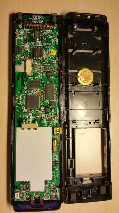
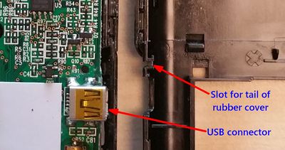
- Once all of the locking tabs are released, gently separate the two shell halves, opening from the right-hand side (seen from the front). The PC board will remain attached to the front shell, but the audio transducer (beeper) is attached to the back shell and is connected to the PC board by two wires secured at the left-hand side of the case. These wires can break off if the case is pulled apart too far on that side. At this point, the rubber cover for the USB connector will likely fall out of the case.


Separating the PCB
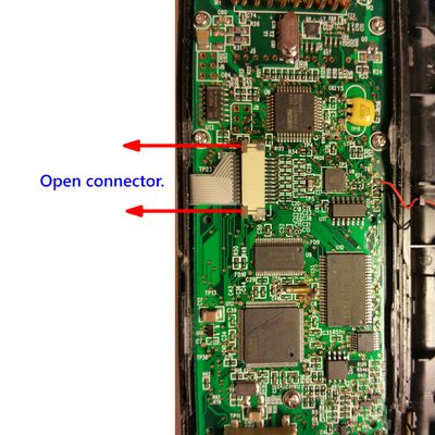
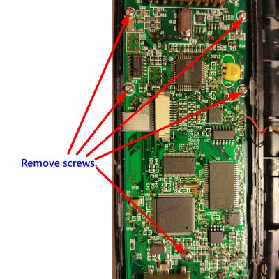
- If you want to separate the PCB from the case, you will need to disconnect two ribbon connectors. The first is visible from the exposed, component side of the PCB. It connects to the touchscreen sensors. Open the connector by pushing the grey tabs toward the ribbon with a small screwdrive or tweezers.
- Now remove the five Philips-head screws securing the PCB to the front shell and gently pull (or pry) out the PCB. It is held on the side by bulges on the shell and is still connected to the display by a ribbon connector on the solder side.
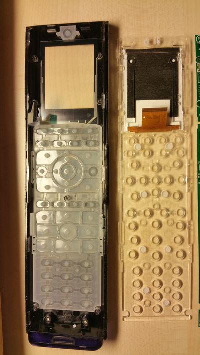
- At this point, it is best to remove the acrylic plate on which the display is mounted from the front shell together with the PCB. The keys can be left lying in the front shell.
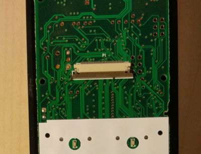
- The ribbon connector on the PCB's component side, which connects to the display, can be opened in a similar way to the touchscreen ribbon connector. However, this requires going in separately from each side to push the (gray) lock away from the (white) connector body (i.e. down). Due to the leverage exerted by pushing on one side of the connector lock at a time, you may need to repeat this process before you can pull the ribbon out of the connector.


Reassembly
- When reconnecting the display ribbon connector, hold the acrylic display carrier parallel and close to the solder side of the PCB and slide it upward against the PCB, first gently, until you are sure that the ribbon has entered evenly into the connector slot, then with more force to force to ribbon into the connector contacts. The acrylic plate needs to be quite close to the PCB to attain the needed force to reseat the ribbon in the connector.
- Once the ribbon is properly inserted into the connector, reclose the connector by pressing the (gray) locking bar toward the (white) connector body (i.e. up) from each side. As when opening the connector, you may need to repeat this due to the leverage exerted by pushing on one side of the connector lock at a time.
- Remember to reseat the rubber cover for the USB connector in the back shell before putting the shell back together. The tail of the rubber cover fits into a slot in the back shell.
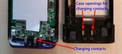
- When putting the case back together, ensure that the charging contacts on the PCB are properly aligned with the corresponding openings in the back shell before snapping the case together. Failure to do so can result in cracking the back shell.