 |
JP1 Remotes
|
| View previous topic :: View next topic |
| Author |
Message |
digitaltoast
Joined: 25 Nov 2012
Posts: 3
Location: United Kingdom
|
 Posted: Sun Nov 25, 2012 11:11 am Post subject: URC 7210 - definitive JP1 version needed. Pic attached. Posted: Sun Nov 25, 2012 11:11 am Post subject: URC 7210 - definitive JP1 version needed. Pic attached. |
 |
|
I've got 3 perfectly good OFA URC-7210, AKA "Big Easy" remotes which could do with some JP1 love.
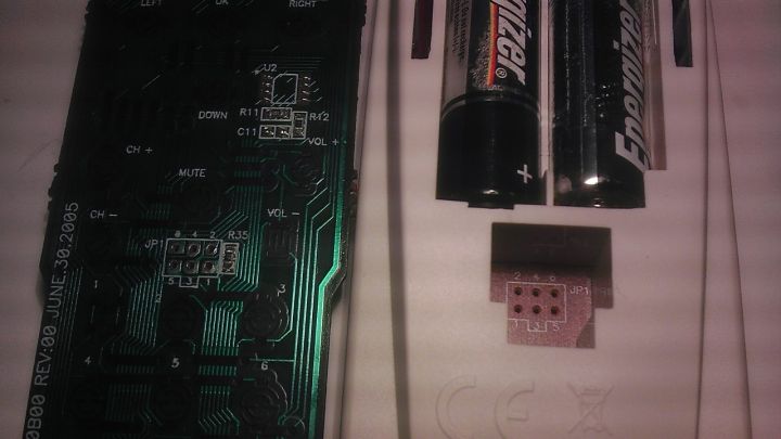
But after hours of Googling and asking a supplier of JP1 cables a question, I'm confused. Here's a pic (sorry, crappy phone camera):
The supplier said that despite it saying JP1, they THOUGHT it was actually a JP1.2 connection - the total inc postage would be close to £40. And it's a long way to return if the wrong one! Obviously, I realise I need to solder on my own header pins, but I've decided to make my own cable, probably the Arduino-based project seeing as I've got an Arduino kicking around.
As I understand it, JP1 is for EEPROM based URCs and JP1.2 is for FLASH (ie: single MCU like mine) based URCs.
EDIT: Just found this http://www.hifi-remote.com/wiki/index.php?title=JP1_Interfaces which says:
| Code: | JP1 indicates a remote with an EEPROM chip
JP1.1 indicates a remote with an SST brand flash chip
JP1.2 indicates a remote with Motorola HCS08 flash chip |
Well it's definitely not EEPROM, so must either be 1.1 or 1.2, but seeing as the chip is a big black lump I can't tell. There's this EXCELlent list of JP1 remotes and their connections, but 7210 isn't listed.
All I can tell you is that it says:
| Code: | | Big Easy MK II 1 Device, URC-11-7210B00 REV:00 JUNE.30.2005 |
which is interesting, because although the case hasn't got any device buttons, the board has button contacts for TV, VCR, DVD and SAT.
On the back is the "backwards RU logo" followed by "E174651", then "HD-7" then "HADTE 0530".
So, any ideas gratefully appreciated!
Last edited by digitaltoast on Sun Nov 25, 2012 12:03 pm; edited 1 time in total |
|
| Back to top |
|
 |
3FG
Expert
Joined: 19 May 2009
Posts: 3367
|
| Posted: Sun Nov 25, 2012 12:01 pm Post subject: |
|
|
Here's a related thread about the URC-7240. There is also a thread at RC which confirms that the 7210 uses 5 digit EFCs, but UEI says it does not have learning.
Anyway, this is very likely to be a JP1 remote. Your picture of the PCB has an 8 pin location labeled U2. That is very likely where the the EEPROM would go. The 7240 thread says that remote didn't have an EEPROM installed. The lack of learning capability also suggest that EEPROM is not installed.
So, look at the other side of the PCB to find out if U2 is populated. If it isn't you'll need to get a 24C16 class (2KB) EEPROM. I think ones with the correct packaging are difficult to find these days. Of course you'll also need to add the JP1 header |
|
| Back to top |
|
|
digitaltoast
Joined: 25 Nov 2012
Posts: 3
Location: United Kingdom
|
| Posted: Sun Nov 25, 2012 12:12 pm Post subject: |
|
|
Thanks 3FG. Lots to read in that other thread!
I don't actually need to make it learn anything new, just reprogram the correct EFCs to the right keys. I know all the codes from this table and I've done in the manual way (as described on that page) but it's incredibly tedious like that.
So is this idea of using JP1 to re-assign existing EFCs to correct a layout actually going to need that EEPROM? Because I can see my soldering "skills" and something that small ending up in smoke and swearing! |
|
| Back to top |
|
|
3FG
Expert
Joined: 19 May 2009
Posts: 3367
|
| Posted: Sun Nov 25, 2012 1:04 pm Post subject: |
|
|
Yes, you need the EEPROM. The JP1 interface doesn't talk to the processor. Instead it uses the I2C serial protocol to read and change the contents of the EEPROM. JP1 can't access the small part of processor memory which is used for the EFC programming that you're doing now.
It is difficult to solder in the EEPROM. Make sure that you get a SOIC (or SOIC8) package, with a width including the leads of 5.8mm. The 16Kbit memory size is safest, but some people have installed 32Kbit EEPROMS and gotten them to work. |
|
| Back to top |
|
|
digitaltoast
Joined: 25 Nov 2012
Posts: 3
Location: United Kingdom
|
| Posted: Sun Nov 25, 2012 2:11 pm Post subject: |
|
|
| 3FG wrote: | | JP1 can't access the small part of processor memory which is used for the EFC programming that you're doing now. |
Ah, not what I wanted to hear, but very helpful and useful to know! Thank you!
| 3FG wrote: | | ...you'll need to get a 24C16 class (2KB) EEPROM. I think ones with the correct packaging are difficult to find these days. It is difficult to solder in the EEPROM. Make sure that you get a SOIC (or SOIC8) package, with a width including the leads of 5.8mm. The 16Kbit memory size is safest, but some people have installed 32Kbit EEPROMS and gotten them to work. |
Well, on the bright side, unless I've got the wrong item, I didn't have any problems finding one and fortunately it's only 65p inc tax. For the hell of it, I'm going to order a couple (bound to toast one with my crappy iron) and see if I can make the Arduino-based programmer... |
|
| Back to top |
|
|
The Robman
Site Owner
Joined: 01 Aug 2003
Posts: 21238
Location: Chicago, IL
|
| Posted: Sun Nov 25, 2012 5:16 pm Post subject: |
|
|
The EEPROM chip looks like, only thing I noticed is that it runs on voltage 2.5v-5.5v. Your remote only has 2 batteries, meaning it's 3v when the batteries are carrying a full charge. I would recommend getting a chip that runs on 1.8v voltage, just to make sure that it will work when the batteries are getting a bit flat. But if you've already ordered this chip, it'll probably work fine.
Also, I can't quite tell from the pic if the resistors in R11, R12 and R35 are all there, also the capacitor in C11. If any of those spots are empty, you may need to populate them.
_________________
Rob
www.hifi-remote.com
Please don't PM me with remote questions, post them in the forums so all the experts can help! |
|
| Back to top |
|
|
|
|
You cannot post new topics in this forum
You cannot reply to topics in this forum
You cannot edit your posts in this forum
You cannot delete your posts in this forum
You cannot vote in polls in this forum
|
Powered by phpBB © 2001, 2005 phpBB Group
|

