| View previous topic :: View next topic |
| Author |
Message |
WagonMaster
Joined: 16 Apr 2009
Posts: 361
|
 Posted: Tue Aug 04, 2009 10:34 am Post subject: Posted: Tue Aug 04, 2009 10:34 am Post subject: |
 |
|
| csete wrote: | | The controller on the USB/serial Cable is a Prolific PL2303 (0x067b:0x2303). Any idea if this is a cable that will work? |
Although my working IoGear GUC232A adapter obviously has a different VID/PID, it uses the Linux 'pl2303' kernel module, so I strongly suspect that your adapter will work.
| csete wrote: | | My JP1 cable is an older JP1.x cable. It has 3 transistors and a couple of capacitors. I don't see any capacitors on the newer schematic. I'm planning to rewrite my JP1 cable to match the latest schematics... perhaps tonight. |
This sounds to me like you built what's currently called the "JP1.1" design but left off the extra parts (Q1, R1, and D1) that would have been needed to actually use it with an ancient JP1.1 remote control. In essence, this would be a JP1.2/JP1.3 interface but with the DTR line controlling the remote's "reset" line, unlike the other 2 designs from Tommy Tyler, both of which use the RTS line to control the reset line.
Personally, I don't think there's any reason to rewire your hardware just yet. I've breadboarded the full JP1.1 interface described above (including Q1, R1, and D1, so I have all 4 transistors and 2 capacitors) and it works fine with my JP1.2 and JP1.3 remote controls (using special software that won't accidentally put a JP1.2 remote into the undesired Background Debug Mode [BDM]).
| vickyg2003 wrote: | | Since your remote is downloading, I don't think its an interface problem, I think you have a software issue. |
I think Vicky is correct, but I'm sure you'd both agree that it's wise to make sure that you don't have more than 1 problem (e.g. software and USB/RS-232 adapter) simultaneously.
Bill |
|
| Back to top |
|
 |
The Robman
Site Owner
Joined: 01 Aug 2003
Posts: 21234
Location: Chicago, IL
|
| Posted: Tue Aug 04, 2009 10:46 am Post subject: |
|
|
I've just scanned back through the previous posts in this thread and I don't see anything that states whether you have a wire connected to pin 5 or not, so could you please clarify that.
When using the out-dated JP1.x designs with a JP1.3 remote, it's important to disconnect pin 5 at the female IDC end of the JP1.x cable. Disconnecting it at the DSUB end is not sufficient because the cable itself will act as some sort of antenna and can cause problems.
_________________
Rob
www.hifi-remote.com
Please don't PM me with remote questions, post them in the forums so all the experts can help! |
|
| Back to top |
|
|
csete
Joined: 09 Jun 2005
Posts: 131
|
| Posted: Tue Aug 04, 2009 10:55 am Post subject: |
|
|
I *do* have pin 5 connected at the moment. I'm aware that needs to change no matter what.
My plan was to rebuild the circuit and make that change at the same time. Based on the other comments, it sounds like I should just break the connection to pin 5 and leave the circuit alone for now... The trick is how to easiest break the connection at that end. I'm considering actually breaking the pin off from the remote's male connector... but that seems drastic. |
|
| Back to top |
|
|
csete
Joined: 09 Jun 2005
Posts: 131
|
| Posted: Tue Aug 04, 2009 10:57 am Post subject: |
|
|
| PS - I'm aware that I'm making things more difficult for everyone by trying to deal with two different problems at the same time... Sorry about that. I'm going to break the pin 5 connection (somehow), otherwise leave the circuit alone and put the Linux support on the back burner until we are able to get further with the RMIR/IR upgrade issue. |
|
| Back to top |
|
|
The Robman
Site Owner
Joined: 01 Aug 2003
Posts: 21234
Location: Chicago, IL
|
| Posted: Tue Aug 04, 2009 11:37 am Post subject: |
|
|
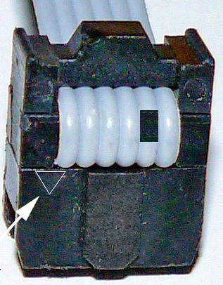
Personally, what I do is cut the wire where it bends around the strain relief in the IDC connector.
The following image attempts to show where I cut the wire.
_________________
Rob
www.hifi-remote.com
Please don't PM me with remote questions, post them in the forums so all the experts can help! |
|
| Back to top |
|
|
csete
Joined: 09 Jun 2005
Posts: 131
|
| Posted: Tue Aug 04, 2009 12:39 pm Post subject: |
|
|
| Thanks. I will give that a shot. |
|
| Back to top |
|
|
WagonMaster
Joined: 16 Apr 2009
Posts: 361
|
| Posted: Tue Aug 04, 2009 12:40 pm Post subject: |
|
|
| csete wrote: | | Based on the other comments, it sounds like I should just break the connection to pin 5 and leave the circuit alone for now... |
That sounds very wise to me....
| csete wrote: | | The trick is how to easiest break the connection at that end. I'm considering actually breaking the pin off from the remote's male connector... but that seems drastic. |
It sounds like you've used an IDC connector and a ribbon cable for your JP1 remote end. That makes things more difficult than they need to be. I'd been meaning to do this for a while, and it may be too late to be useful to you (Craig), but I've finally made some recommendations on the use of better connectors for the remote control end than an IDC connector with ribbon cable.
Bill |
|
| Back to top |
|
|
csete
Joined: 09 Jun 2005
Posts: 131
|
| Posted: Tue Aug 04, 2009 4:54 pm Post subject: |
|
|
Well... that will teach me not to try to do multiple things at once... I was taking Rob's advice to cut the wire as he shows... but rather than count from the left, I just looked at the one remaining (extra) wire to the right. I just cut wire 6 instead of 5. Doh.
How reusable are these IDC connectors? Can I open it up and move it further down the ribbon cable and reuse it or are they basically one-time-use? |
|
| Back to top |
|
|
csete
Joined: 09 Jun 2005
Posts: 131
|
| Posted: Tue Aug 04, 2009 5:03 pm Post subject: |
|
|
| Never mind... I try digging out an old disk drive cable and trying to create another cable again... |
|
| Back to top |
|
|
The Robman
Site Owner
Joined: 01 Aug 2003
Posts: 21234
Location: Chicago, IL
|
| Posted: Tue Aug 04, 2009 5:54 pm Post subject: |
|
|
| csete wrote: | | How reusable are these IDC connectors? Can I open it up and move it further down the ribbon cable and reuse it or are they basically one-time-use? |
You should be able to take it apart and re-use it easily enough. Just don't break the strain relief when you take it off.
_________________
Rob
www.hifi-remote.com
Please don't PM me with remote questions, post them in the forums so all the experts can help! |
|
| Back to top |
|
|
Tommy Tyler
Expert
Joined: 21 Sep 2003
Posts: 412
Location: Denver mountains
|
| Posted: Tue Aug 04, 2009 6:58 pm Post subject: |
|
|
Oops! I wrote an instruction HERE early last year on how to do this and never got around to posting it.
Tommy |
|
| Back to top |
|
|
csete
Joined: 09 Jun 2005
Posts: 131
|
| Posted: Tue Aug 04, 2009 9:29 pm Post subject: |
|
|
| Unfortunately, the connector kind of disintegrated. I have another IDE cable on hand that I'm going to repurpose. I like Bill's idea, but I'm kind of going cheap with "parts on hand"... Unfortunately, this is likely not going to happen immediately, so I can't work on my other issue. I'm hoping to find time tomorrow night and I'm considering just rebuilding the whole circuit at this point since I'm already rebuilding part of it.... |
|
| Back to top |
|
|
csete
Joined: 09 Jun 2005
Posts: 131
|
| Posted: Thu Aug 06, 2009 9:18 pm Post subject: |
|
|
It appears that I've been unsuccessful on my first attempt to rebuild my JP1 cable. Urgh. Reading Tommy's troubleshooting instructions, the reset must be working because I'm getting the blinking lights, but no matching remotes. I'm going to have to walk through the troubleshooting instructions when I have more time to see if I can figure out what I did wrong and where.
One hardware question... I reused the transistors (and only the transistors) when I rebuilt the hardware. I used solder wicking braid to tear apart the old circuit. Any chance the heat of the solder removal could trash a transistor and cause this behavior? I probably should have gone and bought new hardware, but I was too lazy to drive across town.
Thanks,
Craig |
|
| Back to top |
|
|
Tommy Tyler
Expert
Joined: 21 Sep 2003
Posts: 412
Location: Denver mountains
|
| Posted: Fri Aug 07, 2009 7:22 am Post subject: |
|
|
Of course there's always a chance heat can damage the transistors, but it is not very likely unless you really sit on them a long time with the soldering iron.
If you have a digital multimeter with a diode check function you can test a transistor. For an NPN transistor, it should show a diode voltage (less than 1 volt) from base to emitter and from base to collector with the positive test lead on the base, and a "no voltage" value (like a reversed diode) when the leads are reversed. Try it first with an extra diode or rectifier to see what the meter readings look like. This is not as conclusive as checking the beta (amplifier gain), but will often reassure you the transistor is intact. |
|
| Back to top |
|
|
csete
Joined: 09 Jun 2005
Posts: 131
|
| Posted: Fri Aug 07, 2009 7:35 am Post subject: |
|
|
| I have a digital multimeter, but I don't believe it has a diode check function. The first thing I really need to do is walk through the wiring all over again with a fresh head. I'm not really happy with the layout turned out (Frankenstein?)... It is certainly a chance that I screwed something up in the process. Given the low cost of the parts, I may just throw it out (saving the two cables) and start from scratch... |
|
| Back to top |
|
|
|

