Page 2 of 2

Posted: Mon Oct 31, 2011 10:10 am
by JD4x4
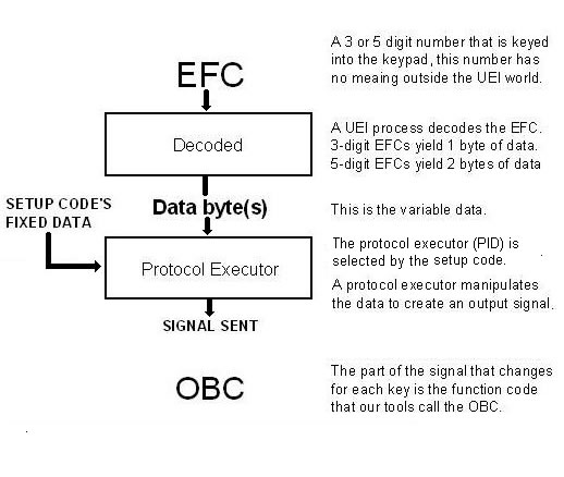
So for the 'visual learners' here (like me), if we take vickyg2003's excellent overview graphic of the process and use: 'Decoded' = (Device:, Sub-device:, Protocol:, and function) in the top 'Decoded' box, Data byte(s) as Hex as the output of decoded into the Protocol Executor, and (binary signal, sent using Protocol:) as the signal output, which =OBC (as decimal), to the 'Signal Sent' part of the diagram... that's pretty much a basic overview and explains the use of the 'details' that eferz used above? (I'm asking if I got it close to right :) )

Or, is OBC actually the 'token' for 'function' in my 'formula' above?

Not trying to beat the horse more, but looking for where the other detail fits in the whole process, in a more visual way.

Posted: Mon Oct 31, 2011 10:55 am
by vickyg2003
Protocol, device and sub device comes from the setup code, the function comes from the Hex decoded from the EFC.

Posted: Mon Oct 31, 2011 11:53 am
by JD4x4
vickyg2003 wrote:Protocol, device and sub device comes from the setup code, the function comes from the Hex decoded from the EFC.
Ahh.. got ya, I think.
So on the left side of your graphic, 'Setup Code's Fixed Data' = (Device:, Sub-device:, Protocol:) as input along with the hex to generate the signal output, which when stripped of it's coded Device and Sub device info (I'm only guessing that the device/sub device info is in the signal) is the device's function signal that we are calling the OBC.

(Sorry.. maybe it's only me that finds it easier to understand this way?)

Posted: Mon Oct 31, 2011 12:08 pm
by vickyg2003
Yes, thats it.

Posted: Mon Oct 31, 2011 1:07 pm
by The Robman
For anyone wondering which graphic JD4x4 is referring to, it's this:

Image

If you like visual images, let's suppose that the following binary signals were captured from your device:

00000010 00000001 00000000 = Number 0
00000010 00000001 00000001 = Number 1
00000010 00000001 00000010 = Number 2
00000010 00000001 00000011 = Number 3

We would probably consider the first byte to be the "device code", the 2nd byte to be the "Sub-device code" and the 3rd byte to be the OBC (or "function code" or "command code", etc). As the first 2 bytes do not change, they can be fixed data. As the last byte does change, it would need to be variable data.

So, the first step UEI would need to do is to create an executor to generate these signals (if they don't already have one). They would program into it all the required info, such as the carrier frequency, etc. They would program it to look for 2 fixed bytes and 1 variable byte.

Next, they would create a setup code to use this executor. The setup code would have a type to match the device (ie, TV, VCR, DVD, etc) and a code number. Behind the scenes, the setup code would also have the id of the protocol executor and the correct fixed data required to generate "00000010 00000001". It would also have a different code assigned to each button.

Just from looking at the (made up) binary signals above, I would determine that this is a MSB protocol, which has a device code of 2 and a sub-device code of 1. The OBCs for the 4 numeric buttons shown are 0,1,2,3.

Posted: Mon Oct 31, 2011 3:08 pm
by JD4x4
Thanks to both of you (vickyg2003 & Robman). That clears it up nicely for me.

I may not be runnin' with the big dogs, but at least I don't feel like I'm chewin' up stuff with the puppies anymore. :wink: