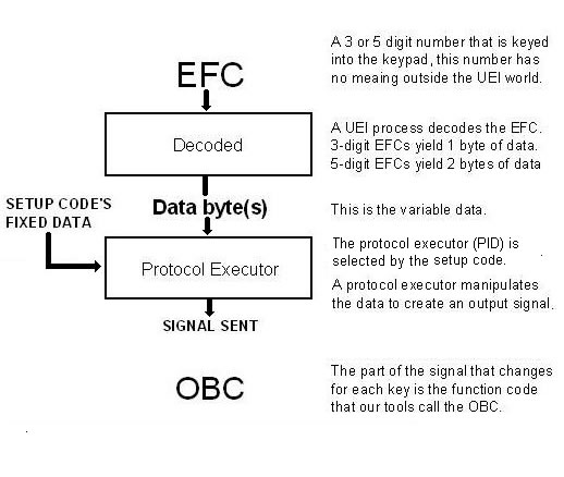
For anyone wondering which graphic JD4x4 is referring to, it's this:
If you like visual images, let's suppose that the following binary signals were captured from your device:
00000010 00000001 00000000 = Number 0
00000010 00000001 00000001 = Number 1
00000010 00000001 00000010 = Number 2
00000010 00000001 00000011 = Number 3
We would probably consider the first byte to be the "device code", the 2nd byte to be the "Sub-device code" and the 3rd byte to be the OBC (or "function code" or "command code", etc). As the first 2 bytes do not change, they can be fixed data. As the last byte does change, it would need to be variable data.
So, the first step UEI would need to do is to create an executor to generate these signals (if they don't already have one). They would program into it all the required info, such as the carrier frequency, etc. They would program it to look for 2 fixed bytes and 1 variable byte.
Next, they would create a setup code to use this executor. The setup code would have a type to match the device (ie, TV, VCR, DVD, etc) and a code number. Behind the scenes, the setup code would also have the id of the protocol executor and the correct fixed data required to generate "00000010 00000001". It would also have a different code assigned to each button.
Just from looking at the (made up) binary signals above, I would determine that this is a MSB protocol, which has a device code of 2 and a sub-device code of 1. The OBCs for the 4 numeric buttons shown are 0,1,2,3.