Hi all
I recently bought an OFA 3440 which I need to upgrade codes to, in order to have it work with
a Durabrand DVD-Player.
I found the following post covering my subject.
While it sounds easy I guess I'd still neeed to know
- layout of circuitry (where to put the EEPROM)
- capacitor for tensions around 24 V ok?
- I couldn't find the RDF mentioned below
- where do the wires have to go?
I already opened the remote, but found no EEPROM socket, is it soldered right in?
What are the limitations of making a not learnable remote JP1 compliant?
Thanks for your advice in advance
Marco
....excerpt from post 'Help URC-3440'......
It has holes for JP1 header and pads for EEPROM.
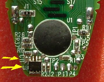
Modification requires JP1 header, EEPROM 24C16 (or 24C08), J6, J7, J8 wires and capacitor C11 (0.1uF).
It uses new style keymoves like URC-6131, has no macro support, recognizes only first 1K of 24C16.
RDF is here:
http://groups.yahoo.com/group/jp1/files ... l%204).rdf
Rob please can you check DigitMaps section and approve or change indexes 160 and 161.
EEPROM images (virgin and with sample upgrades) are here:
http://groups.yahoo.com/group/jp1/files ... c-3440.zip[/quote]
Make URC-3440 compatible
Moderator: Moderators
Re: Make URC-3440 compatible
EEPROM goes to spot marked U2While it sounds easy I guess I'd still neeed to know
- layout of circuitry (where to put the EEPROM)
Irrelevant, it is ceramic capacitor, not electrolytic and highest voltage in this remote is 3V.- capacitor for tensions around 24 V ok?
RDF is with other RDF files in RDF pack- I couldn't find the RDF mentioned below
https://www.hifi-remote.com/forums/viewtopic.php?t=3784
- where do the wires have to go?
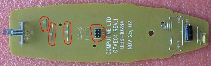
Yes, look at first picture.I already opened the remote, but found no EEPROM socket, is it soldered right in?