I am currently very interested in interfaces based on non-FTDI chips, so I would be very grateful if you could post a link to the CH341-based interface that you used.powersola wrote:After trying another interface (CH341-based) all worked great.
CH340G USB-to-Serial converter
Moderator: Moderators
Split from here: http://www.hifi-remote.com/forums/viewt ... p?t=102842
Graham
Yeah, sure.mathdon wrote:I am currently very interested in interfaces based on non-FTDI chips, so I would be very grateful if you could post a link to the CH341-based interface that you used.powersola wrote:After trying another interface (CH341-based) all worked great.
That's the exact one I have, ordered here:
https://www.aliexpress.com/item/32761423124.html
I soldered the missing pins, as you can see from aliexpress it's missing CTS and RTS headers.
https://imgur.com/v5iOcjh
https://imgur.com/VJsWitM

For the price (very low) it works wonderfully. Never had a problem.
I also have a real FT232RL interface. Actually it's a transplant. I had a clone board, the usual red one you see everywhere, to which I soldered on a genuine FT232RL chip from RS Electronics (which is itself 3 times more expensive than the entire clone board)
Have a nice day,
Federico
Hi Mathdon,
I have used the CH340 cables with RM V2.10 Build 3, These cables work well on my remotes.
The cable only has 4 wires VCC, GND, RXD and TXD. I opened the hood and exposed the ch340 chip. The board has unconnected pads for RTS and CTS.
I just removed the VCC (red wire) and attached it to RTS.
(VCC is not needed since I am running the remote on batteries).
The cables are really cheap (under $1 from China).
I received a few cables that were duds, displaying gibberish in a terminal test so you take your chances buying cheap cables like this from China.
yes powersola you just need RXD, TXD, GND and RTS.powersola wrote:I connected it this way and it works wonderfully:
https://imgur.com/YGV0pL7
Federico
I am not comfortable connecting VCC to ANY remote from any module or cable.
I always prefer to use the remotes power source in the remote.
I had a very old atlas remote that is dead now because of this. (connecting 5V to a 3V remote)
I suspect the newer remotes have some kind of protection but I still prefer to use the batteries in the remote to power the remote.
Not only with RMIR, but I can tell these little cheap interfaces are working wonderfully with almost everything I tried (STBs, solar inverters, managed switches, and more). Way better than the fake FT232RL-based boards out in the wild (some are OK, some not.. with the one I have on hand here I couldn't even download data from RMIR...).mathdon wrote:Thanks to all for your info. I am pleased to know that these CH340 interfaces with RTS connected work well with RMIR.
Of course a real FT232RL chip is OK, it's the state of the art, but it's really hard to take a hand on it for cheap.
Think about it: even RS-electronics, some years ago, suffered from clone plague (shipped lots of fake FT232RL chips, probably something went wrong in the distribution chain... and I was affected too, discovered it after many headaches of non working Kenwood ham-radio interfaces assembled....).
For 1€ it's really worth to buy a CH340g interface and keep it around, it's always useful and it's working reliably.
Federico
For that price it's an "acceptable downside", even if I encountered that problem very rarely buying since 20 years from china. But could happen.ckeays wrote:Hi Mathdon,
I received a few cables that were duds, displaying gibberish in a terminal test so you take your chances buying cheap cables like this from China.
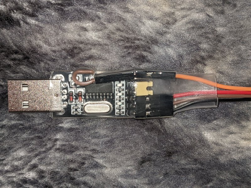
My CH340G interface, the one in the photo, did even come with a jumper installed between TX and RX pins.
For everybody, a good starting point would be to "jumper" (connect together) TX and RX pins, open the COM port in a terminal (for example minicom, hyper-terminal, termite, etc...), and write something random.
If you receive back from the terminal exactly what you type 99,9% chances is that the interface is working good
I needed another JP1.X cable. I had ordered these for another project that involved ttl console access.
https://www.amazon.com/gp/product/B00LZV1G6K
They are CH340 based, but these didn't bring out RTS. So, I looked at the datasheet for the CH340G and RTS is on pin 14. Building it was very easy. I just soldered a male jumper onto the chip and hooked everything up. Here is the result. It works perfectly. So, there's another option.
StephenR0, something similar happened to me, but I explicitly order the "pink" one with 6 pins, for a little higher price. But when it came it was the cheaper 4pin one.
This is the exact item I bought, so you don't waste your money on this seller.
https://www.aliexpress.com/item/PL2303- ... 4c4dNxwTGv
However, opening the pink shell, I traced the necessary pin on the chip and it went on the underside, on a empty pad. I desoldered the 5V cable that's not necessary for our matter, and soldered in the right place. I attach some photos.