At the top of this page is a link to the File Section, from there you would follow the link to the Device Upgrades folder, which has separate sub-folders for each "type" of device (ie, TV, DVD, VCR, etc)tranx wrote:I shall look for an upgrade library and see if my devices are already there.
Build a JP1.x/JP2 cable using an FTDI Serial Converter Cable
Moderator: Moderators
-
The Robman
- Site Owner
- Posts: 21941
- Joined: Fri Aug 01, 2003 9:37 am
- Location: Chicago, IL
- Contact:
Rob
www.hifi-remote.com
Please don't PM me with remote questions, post them in the forums so all the experts can help!
www.hifi-remote.com
Please don't PM me with remote questions, post them in the forums so all the experts can help!
-
underquark
- Expert
- Posts: 874
- Joined: Mon Jun 20, 2005 4:58 am
- Location: UK
FTDI interface for cheapskates
Thank's, as ever, Tommy for your work.
6-pin plugs seem hard to come by in the UK. I found one source selling them for £0.30 per unit plus £2.40 postage for orders up to the value of £50 but I couldn’t tell if that included contacts or what the minimum purchase quantity was and I was too lazy to e-mail them. Previously I have just hacked the end off a 40-wire HDD cable but on this occasion I ordered a FTDI cable with the 6-in-a-row connector attached (it was actually cheaper than the wire-ended one). I cut it in half, re-arranged the wires and made myself a connector. No 2 x 3 connector, co crimps etc. needed.
6-pin plugs seem hard to come by in the UK. I found one source selling them for £0.30 per unit plus £2.40 postage for orders up to the value of £50 but I couldn’t tell if that included contacts or what the minimum purchase quantity was and I was too lazy to e-mail them. Previously I have just hacked the end off a 40-wire HDD cable but on this occasion I ordered a FTDI cable with the 6-in-a-row connector attached (it was actually cheaper than the wire-ended one). I cut it in half, re-arranged the wires and made myself a connector. No 2 x 3 connector, co crimps etc. needed.
Link to How To document.Preferably mount the connector in a small vice or clamp or, at least, on a flat and well-lit surface.
Orientate the connector with cable to your left, contact openings to your right, black wire furthest away from you.
Grasp the Orange wire and gently push it to your right to reveal a small gap between the plastic retainer on the connector housing and the metal contact. Insert a thin, pointed probe (or slightly blunt needle or bodkin or even a toothpick) into the gap, under the plastic retainer and carefully lever it up whilst gently pulling on the wire as you do so . There will be two "bumps" of metal to overcome. This should allow the cable and contact to be withdrawn from the connector housing.
Repeat for the Yellow wire and for the Red wire and their contacts.
Cut the Brown wire flush with its contact (and just leave the contact in the connector housing).
Cut the Red wire off its contact.
Retract and insulate the Red and Brown wires.
Cut through the channel in the connector housing that had been occupied by the Red wire and contact to split the connector into two (not equal-sized) pieces.
Insert the Yellow wire and contact where the Orange one used to be.
Insert the Orange wire and contact where the Yellow one was.
Place the smaller piece of connector over the larger so that the Black wire and contact line up with the middle hole (now containing the Orange wire). Glue in place. Trim any rough edges.
Last edited by underquark on Thu Jun 07, 2012 5:05 pm, edited 1 time in total.
-
underquark
- Expert
- Posts: 874
- Joined: Mon Jun 20, 2005 4:58 am
- Location: UK
For information for any UK JP1-ers, I bought this item from a good eBay seller for £13.08 including postage. After hacking it as described, above, it's working well using IR7 in Windows XP. (I'll get around to trying it with a more up-to-date version of IR or RMIR in linux it's just that's what I have running on my machine that I tried it on).
Post Office decided the package was just too big to squeeze through their template and charged me extra but the seller refunded this immediately I told him so worth buying from him if you're in the UK/Europe and interested in the 6-in-a-row plugged cable like I used.
Post Office decided the package was just too big to squeeze through their template and charged me extra but the seller refunded this immediately I told him so worth buying from him if you're in the UK/Europe and interested in the 6-in-a-row plugged cable like I used.
-
sloppyedwards
- Posts: 6
- Joined: Tue Jun 12, 2012 6:21 am
Re: FTDI interface for cheapskates
Brilliant! I may try the same thing with this cable: http://www.foogra.com/products/43394/underquark wrote:I ordered a FTDI cable with the 6-in-a-row connector attached (it was actually cheaper than the wire-ended one). I cut it in half, re-arranged the wires and made myself a connector. No 2 x 3 connector, co crimps etc. needed.
Confirmed that this cable works as well:
http://www.ebay.com/itm/New-USB-to-TTL- ... 3f180fb1db
$11.19 USD, free shipping internationally, and confirmed to use the FTDI 232R chip (Win7-64 found drivers automagically). No problems using this cable with the JP1 adapter either.
http://www.ebay.com/itm/New-USB-to-TTL- ... 3f180fb1db
$11.19 USD, free shipping internationally, and confirmed to use the FTDI 232R chip (Win7-64 found drivers automagically). No problems using this cable with the JP1 adapter either.
FWIW about a year ago I purchased the same cable but with a 6 pin single row connector and released the pins from the connector housing and installed them into a 2 x 3 connector housing in the appropriate JP1 arrangement. No need to purchase pins and crimp them onto the wires. It works fine as expected.
This is the cable I purchased:
http://www.digikey.com/product-detail/e ... ND/1836393
This is the cable I purchased:
http://www.digikey.com/product-detail/e ... ND/1836393
-
The Robman
- Site Owner
- Posts: 21941
- Joined: Fri Aug 01, 2003 9:37 am
- Location: Chicago, IL
- Contact:
The reason that Tommy is telling people to use crimps, etc now is in order to make a connector that's much smaller than the traditional IDC connectors that we used to use. This is because UEI is making much smaller openings for the 6-pin these days.
Rob
www.hifi-remote.com
Please don't PM me with remote questions, post them in the forums so all the experts can help!
www.hifi-remote.com
Please don't PM me with remote questions, post them in the forums so all the experts can help!
-
underquark
- Expert
- Posts: 874
- Joined: Mon Jun 20, 2005 4:58 am
- Location: UK
No issue there. I'm using a connector housing that is the same size as the one Tommy said to use. I simply lifted the release tab on each pin position of the 1x6 non-IDC connector that came on the cable, slid pin/wire combos out the back end and inserted them into the 2x3 non-IDC connector housing. As I said, no crimping needed. No use of IDC anything.The Robman wrote:The reason that Tommy is telling people to use crimps, etc now is in order to make a connector that's much smaller than the traditional IDC connectors that we used to use. This is because UEI is making much smaller openings for the 6-pin these days.
In a pinch, you could cut the 1x6 connector housing on the cable that I linked, into 2 pieces. You lose one position in the cutting. So, you'd end up with a 2 position 1 row connector housing and a 3 position 1 row housing. You only need 4 pins total, a 3 position and a 1 position would work. Super glue them back to back, poke the wire/pin combos in and you're done.
-
The Robman
- Site Owner
- Posts: 21941
- Joined: Fri Aug 01, 2003 9:37 am
- Location: Chicago, IL
- Contact:
Do you have pics or part numbers that would help me visualize what you're doing?cauer29 wrote:I'm using a connector housing that is the same size as the one Tommy said to use. I simply lifted the release tab on each pin position of the 1x6 non-IDC connector that came on the cable, slid pin/wire combos out the back end and inserted them into the 2x3 non-IDC connector housing. As I said, no crimping needed. No use of IDC anything.
Rob
www.hifi-remote.com
Please don't PM me with remote questions, post them in the forums so all the experts can help!
www.hifi-remote.com
Please don't PM me with remote questions, post them in the forums so all the experts can help!
Here's the cable that I purchased. It is a variant of the one Tommy says to buy. The only difference is that this one has a 6 position single row connector vs bare wires on the Tommy version.The Robman wrote:Do you have pics or part numbers that would help me visualize what you're doing?cauer29 wrote:I'm using a connector housing that is the same size as the one Tommy said to use. I simply lifted the release tab on each pin position of the 1x6 non-IDC connector that came on the cable, slid pin/wire combos out the back end and inserted them into the 2x3 non-IDC connector housing. As I said, no crimping needed. No use of IDC anything.
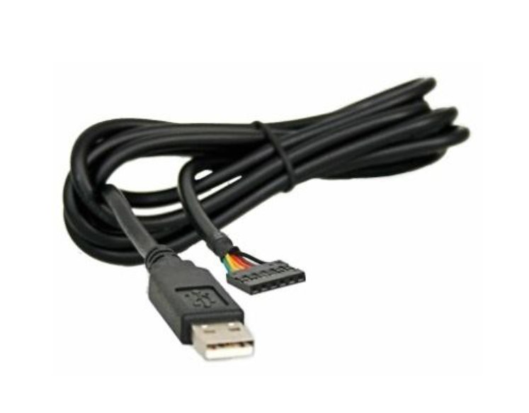
The FTDI part number for the cable that I purchased is:
TTL-232R-3V3 (digikey 768-1015-ND)
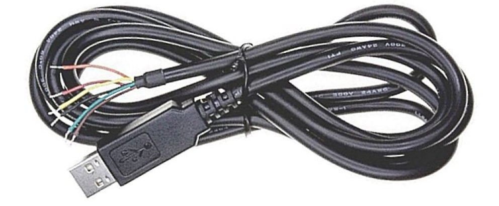
The one Tommy says to get is identical but it has raw wire ends rather than a 6 x 1 connector.
TTL-232R-3V3-WE (digikey 768-1016-ND)
The "WE" means wire ends. It looks like this:
If you look carefully at the 6 x 1 connector on the cable that I purchased, you can see a little tiny plastic flap on the connector housing for each pin. You lift the flap for a pin and pull back on the wire. The wire with crimped pin attached slides out the back of the connector.
Here's a picture showing the flaps:

Do this for all six pins. Install the 4 required wires with already crimped pins into the exact same 2 x 3 connector housing that Tommy says to use, following his instructions for which wire color goes to which position.
edit: turns out it's not the exact same connector but one that is very similar:
Digikey 609-2380-ND FCI 69176-006LF. I didn't bother to purchase the connector, but just harvested the connector from an old computer case.

In the end, you have a cable that is 100% physically identical to what you would have following Tommy's instruction completely. The only difference is that you didn't need to buy any crimp pins and you didn't need to crimp them to the bare wires. You need only a modicum of dexterity to extract the pins with wires attached, from the 6 x 1 connector. Then again if you go the Tommy route, you have to have the skill to crimp the pins onto the bare wires. I personally think that my method is less work, less money and less skill required.
-
The Robman
- Site Owner
- Posts: 21941
- Joined: Fri Aug 01, 2003 9:37 am
- Location: Chicago, IL
- Contact:
I like it, thanks for posting.
Rob
www.hifi-remote.com
Please don't PM me with remote questions, post them in the forums so all the experts can help!
www.hifi-remote.com
Please don't PM me with remote questions, post them in the forums so all the experts can help!
-
The Robman
- Site Owner
- Posts: 21941
- Joined: Fri Aug 01, 2003 9:37 am
- Location: Chicago, IL
- Contact:
Well, Tommy liked cauer29's idea too, so he's updated the main doc accordingly
https://www.hifi-remote.com/forums/dload ... e_id=10864
https://www.hifi-remote.com/forums/dload ... e_id=10864
Rob
www.hifi-remote.com
Please don't PM me with remote questions, post them in the forums so all the experts can help!
www.hifi-remote.com
Please don't PM me with remote questions, post them in the forums so all the experts can help!